
When a fiber optic cable run fails or underperforms, you need more than a visual inspection to find out why. That’s where OTDR testing comes in, it’s a diagnostic method that uses pulses of light to map an entire fiber optic link, pinpointing exactly where problems like breaks, bad splices, or excessive bends occur. For anyone managing or building out a commercial fiber network, understanding this process is essential to protecting your infrastructure investment.
At CommX Networks, we install and maintain fiber optic cabling for commercial facilities across Southwest Florida, warehouses, office complexes, distribution centers, and more. OTDR testing is part of how we verify that every fiber run we install meets performance standards before we hand it off. It’s also how we diagnose issues fast when an existing link starts causing trouble, without tearing into walls or ceilings to trace cable by hand.
This article breaks down the full picture: what an OTDR actually is, the physics behind how it works, what specific events and measurements it captures, and why those results matter for your network’s long-term reliability. Whether you’re an IT director evaluating a contractor’s test results or a facility manager trying to understand a fiber issue, you’ll walk away with a clear, practical understanding of OTDR testing and how it applies to real-world commercial environments.
Why OTDR testing matters in fiber networks
Fiber optic cabling is the backbone of modern commercial networks. It carries enormous amounts of data at high speed across long distances, and when it works correctly, it’s nearly invisible. When it doesn’t, the consequences range from slow throughput and packet loss to complete link failure. Understanding what is OTDR testing and why it matters gives you the visibility you need to catch problems before they become operational emergencies.
The cost of unverified fiber runs
A fiber run that passes a basic continuity check can still fail to meet performance specifications in ways that only show up under real network load. A technician can verify that light travels through a cable from one end to the other, but that tells you nothing about signal loss, reflections, or how much margin the link has before it degrades. Without OTDR testing, you’re essentially accepting a cable run on faith.
Accepting a fiber run without OTDR verification is like accepting a structural report on a building without any load testing. The numbers on paper may look fine right up until something breaks.
In a commercial environment, the cost of that assumption adds up fast. If a high-loss splice on a critical backbone link goes undetected during installation, it may not cause immediate failure. Instead, it sits there degrading the link’s performance headroom. Over time, as transceivers age or temperatures fluctuate, that margin disappears and the link goes down during production hours. Tracking the fault at that point requires pulling test equipment, interrupting operations, and spending diagnostic time that a proper post-installation OTDR test would have prevented entirely.
Why visual inspection and continuity testing fall short
Physical inspection catches obvious problems, a crushed conduit, a visible break, or a connector that didn’t seat correctly. A basic continuity tester can confirm that light passes through. Neither method tells you where along the cable the performance is degrading, how much signal loss each splice or connector is contributing, or whether a bend in the cable has exceeded the minimum bend radius and is already causing measurable attenuation.
Fiber optic signals operate on a budget. Every component in the link, connectors, splices, cable length, splitters, consumes a portion of the available signal power. If the individual losses add up beyond what the transceiver pair can tolerate, the link fails. You cannot calculate that budget accurately without measuring each component, and you cannot measure each component without an OTDR. Relying on visual checks alone means you’re working blind on every link that doesn’t have an obvious physical defect.
How OTDR results protect your investment
For new construction and facility expansions, OTDR test results serve as documentation. They give you a baseline reading for every fiber run in the building. When a link starts underperforming six months or two years later, you can run a new OTDR sweep, compare it against the original baseline, and immediately identify what changed and where. That comparison can cut diagnostic time from hours to minutes.
For existing facilities with aging fiber infrastructure, OTDR testing gives you an accurate picture of current link health before you invest in new active equipment. There’s no point in upgrading switches and transceivers to support higher speeds if the underlying fiber runs have marginal loss budgets or failing splices that will cause problems at higher data rates. Running OTDR sweeps first tells you exactly where your cabling stands and what, if anything, needs to be repaired or replaced before you spend money on new hardware.
This kind of data-driven approach to infrastructure management is standard practice in well-run commercial environments. It keeps your network documentation current, supports faster troubleshooting, and gives you defensible evidence of installation quality, which matters when holding contractors accountable for the work they deliver.
How OTDR testing works step by step
An OTDR connects to one end of a fiber optic cable and sends short, controlled pulses of laser light down the fiber. Those pulses interact with the glass as they travel, and a small portion of that light scatters back toward the instrument. The OTDR captures that returning light with a highly sensitive photodetector and uses the timing and intensity of the return signal to build a complete picture of the fiber link from a single access point.
The light pulse injection process
Before the OTDR injects any pulses, you set key parameters: the fiber type (single-mode or multimode), the index of refraction for the cable, the pulse width, and the measurement range. Getting these settings right matters because the instrument uses the index of refraction to calculate distance. If you enter the wrong value, every distance reading on the trace will be off. Most modern OTDRs include preset profiles for common fiber types, which significantly reduces the chance of setup errors.
Once you configure the parameters, the OTDR fires pulses at a defined rate. Shorter pulses give you better resolution for identifying events that are close together, while longer pulses travel farther and work better for testing extended cable runs in large facilities or campus environments.
How backscatter and reflections return data
As each laser pulse travels through the fiber, two things happen simultaneously. First, the glass scatters a small, predictable percentage of the light backward through a process called Rayleigh scattering, which is continuous and uniform in a healthy cable, so any deviation from that baseline signals a problem. Second, physical events like connectors, splices, and breaks create discrete reflections that appear as sharp spikes or drops on the trace.
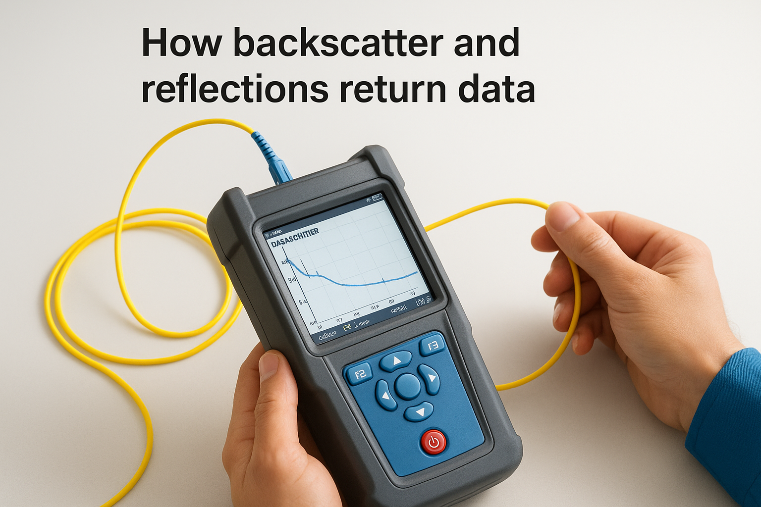
The contrast between uniform backscatter and a sudden spike or dip is precisely what the OTDR uses to locate and classify every event along the link.
Reading time as distance
The OTDR records how long each returning signal takes to arrive back at the instrument. Since light travels through fiber at a known speed, the instrument converts that travel time directly into distance by multiplying the speed of light in the fiber by the elapsed time, then dividing by two. That division accounts for the round trip the pulse takes down the cable and back.
This is how what is OTDR testing comes down to in practice: a time-of-flight measurement that produces a precise location map of your entire fiber run. The result gives you every event on the link with accurate distance markers, so you know exactly where to look when something is wrong.
What an OTDR measures and key terms
Understanding what an OTDR measures helps you interpret test results correctly and make informed decisions about your fiber infrastructure. The instrument captures several distinct types of data as it analyzes a link, and each measurement tells you something specific about the health and performance of that cable run. Knowing these terms is also critical when reviewing documentation from your installation contractor or comparing test results over time.
Attenuation and optical loss
Attenuation is the reduction in signal strength as light travels through the fiber, and it’s the most fundamental measurement an OTDR provides. The instrument measures attenuation in decibels per kilometer (dB/km), comparing the power of the transmitted pulse against what returns at each point along the cable. Higher attenuation means more signal loss, which directly reduces the performance margin of your link.
Every fiber link has a loss budget, a maximum total attenuation that the transceiver pair at each end can tolerate before the link stops working reliably. What is OTDR testing really measuring here is how much of that budget each section of cable, each connector, and each splice is consuming. The key loss contributors the OTDR identifies include:
- Connector loss: typically 0.3 to 0.5 dB per mating pair in a well-installed run
- Splice loss: fusion splices should fall under 0.1 dB; mechanical splices may run higher
- Bend loss: sharp bends past the cable’s minimum bend radius cause localized attenuation spikes
- Cable attenuation: cumulative loss from the fiber glass itself across the full run length
Reflectance and optical return loss
Reflectance measures how much light bounces back toward the OTDR at a specific event point, typically a connector or a cable end. The instrument expresses this as a negative dB value, and a lower (more negative) number means less unwanted reflection, which is better for your link. Optical return loss (ORL) captures the cumulative reflectance across the entire link rather than at a single event.
High reflectance at a connector often indicates a dirty or damaged end face, a problem that cleaning or replacing the connector will fix before it degrades the link further.
Dead zones and event spacing
Dead zones are the short stretches of fiber immediately after a high-reflectance event where the OTDR’s detector is temporarily saturated and cannot accurately measure another event. There are two types: the event dead zone, which affects detection of the next event’s start point, and the attenuation dead zone, which affects accurate loss measurement. Tighter dead zones mean the instrument can resolve events that sit close together on the link, which matters in dense patch panel environments or short cable runs inside a commercial facility.
How to set up and run an OTDR test
Running an OTDR test correctly starts well before you press the measurement button. Preparation and parameter configuration determine whether your results are accurate and usable. Skipping steps or entering incorrect settings can produce traces that look clean but contain measurement errors that hide real problems in your fiber run.
Use a launch cable to eliminate the near-end dead zone
The first thing you need before connecting the OTDR to your fiber link is a launch cable, also called a launch reel or pulse suppressor cable. This is a spool of known-good fiber, typically 50 to 100 meters long, that you place between the OTDR port and the actual cable under test. The launch cable absorbs the initial dead zone created by the instrument’s connector, so the OTDR can accurately measure the very first event on your link rather than missing it entirely.
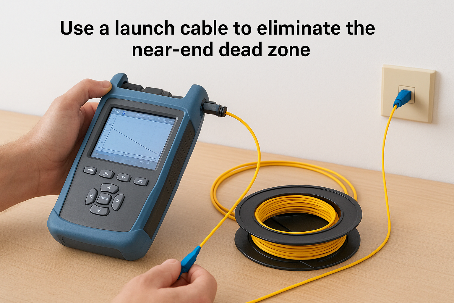
Without a launch cable, the near-end connector on your fiber run sits inside the dead zone, and you get no reliable data on that connection at all.
You also want to use a receive cable at the far end of the link for the same reason. It ensures that the final connector on the cable under test appears clearly on the trace rather than getting cut off at the measurement boundary.
Configure the OTDR parameters correctly
Once your launch cable is in place, enter the correct fiber type and index of refraction into the OTDR before running any measurement. Single-mode and multimode fiber have different refractive indices, and using the wrong value shifts every distance reading on your trace. Most instruments let you select from preset fiber profiles, which is the fastest and most reliable way to get this right.
Set your pulse width and range based on the cable length you’re testing. Short runs inside a commercial facility, under 500 meters, benefit from narrow pulse widths that resolve closely spaced events. Longer backbone runs require wider pulses to maintain signal strength across the full distance. Many technicians run two sweeps at different pulse widths and compare them, giving you both resolution and range coverage in a single session. Understanding this step is central to understanding what is OTDR testing in practice, since no amount of analysis recovers data lost to a misconfigured instrument.
Execute the test and save the results
Start the measurement and allow the OTDR to complete its averaging process, which combines multiple sweeps to reduce noise in the trace. Once the instrument finishes, review the trace on screen to confirm it shows a clean start point, a recognizable slope from cable attenuation, and a clear end reflection. Save the results in the standard SOR file format so you can open them later in analysis software or share them with your network team for baseline documentation.
How to read an OTDR trace and event table
Once your OTDR finishes measuring, it generates two outputs you need to interpret together: the graphical trace and the event table. The trace is a plotted line showing signal power on the vertical axis against distance on the horizontal axis. The event table lists every detected point of interest along that distance with numerical measurements attached to each one. Learning to read both outputs is the practical skill that makes understanding what is OTDR testing genuinely useful in the field.
Understanding the trace slope and event markers
The diagonal slope running from left to right across the trace represents the cable’s continuous signal loss over distance. A healthy fiber run shows a steady, uniform slope that matches the manufacturer’s specified attenuation coefficient for that cable type. If the slope steepens suddenly at a specific point, the fiber is experiencing higher-than-normal loss in that section, which typically points to a tight bend, a damaged section, or a poorly routed conduit.
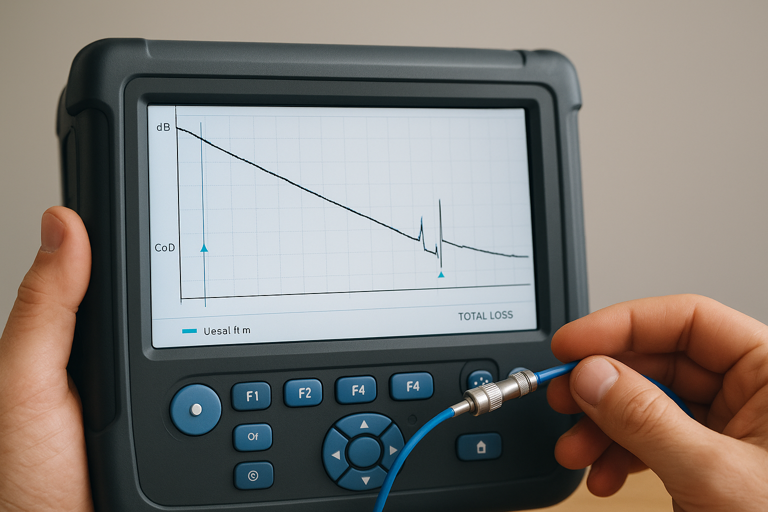
Sharp vertical spikes on the trace indicate reflective events, most commonly connectors or open cable ends. A sudden downward step without a corresponding spike indicates a non-reflective event like a fusion splice or a localized crush point. The depth of that step tells you exactly how much loss that event is contributing to your total link budget. Any spike or step that falls outside your expected thresholds needs attention before you accept the installation.
A non-reflective drop that appears midway through a cable run where no splice should exist is a strong indicator of physical damage to the fiber.
Reading the event table
The event table translates the graphical trace into a numbered list that gives you precise data for each detected event. Each row shows the event’s distance from the OTDR, the event type, the insertion loss at that point in dB, and the reflectance value. At the bottom of the table, the instrument summarizes the total optical return loss and total insertion loss for the entire link.
Work through the table from top to bottom, comparing each event’s loss value against your link’s acceptable thresholds. Flag any connector showing loss above 0.5 dB or any splice exceeding 0.1 dB for fusion work. If the cumulative loss at the final event exceeds your link budget, you have a failing run that needs correction before any active equipment goes live on that fiber path.
Common OTDR testing use cases and limits
Understanding what is OTDR testing in theory is only part of the picture. Knowing when to apply it and where it falls short keeps you from over-relying on a single tool or deploying it in situations where it won’t give you accurate, usable results. Both matter equally if you want to manage fiber infrastructure with confidence.
Where OTDR testing delivers the most value
The most common use case is post-installation verification for new fiber runs. Before you accept a cabling project and allow active equipment to go live, an OTDR test gives you documented proof that every connector, splice, and cable section meets your loss budget. That documentation protects you if performance problems surface later and gives your team a concrete baseline to compare against future test results.
Fault location and troubleshooting is the second major use case. When a fiber link goes down or starts dropping packets, an OTDR can pinpoint the problem event within a meter or two without any physical access to the cable path. For a warehouse or large commercial facility where conduit runs hundreds of meters through walls, ceilings, and raised floors, that precision is the difference between a quick repair and a full-day investigation.
OTDR testing also plays a direct role in maintenance planning, since a trace that shows a splice approaching its loss limit tells you it needs attention before it causes an outage rather than after.
Periodic testing on high-traffic backbone fiber is another strong fit, particularly in environments with equipment vibration, temperature swings, or frequent physical changes near cable pathways. Running scheduled sweeps on critical links and comparing results against your original baseline lets you catch gradual degradation early, before it shows up as dropped connections or reduced throughput during business hours.
Where OTDR testing has real limits
The OTDR has specific constraints you need to account for before relying on it exclusively. Short cable runs under 10 meters often fall entirely within the instrument’s dead zone, making it impossible to accurately measure events that close to the launch point. A well-configured launch cable extends that usable range, but very short patch connections inside a rack still require optical power meter and light source testing to get reliable loss readings.
Dense connector environments present another challenge. When multiple connectors sit close together in a high-density patch panel, tight event spacing causes individual events to merge on the trace, making it difficult to assign loss values to specific connectors. In those cases, combining OTDR results with insertion loss measurements from a dedicated light source and power meter gives you the complete picture that neither tool provides alone.
Quick recap and next steps
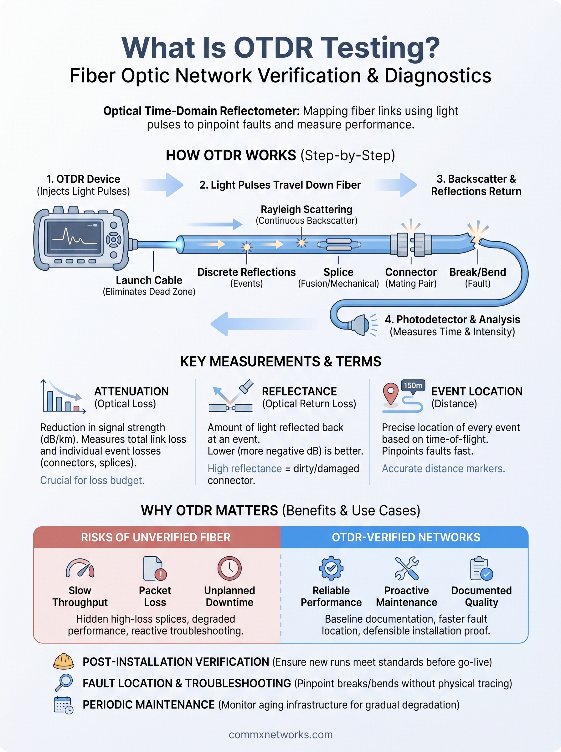
OTDR testing is a precise, data-driven method for verifying and troubleshooting fiber optic links by measuring signal loss, reflectance, and event locations from a single access point. Understanding what is OTDR testing means knowing that it gives you documented proof of installation quality, an accurate baseline for future comparisons, and fast fault location when something goes wrong on your network.
For commercial facilities in Southwest Florida, the stakes are real. A failed fiber backbone in a warehouse or distribution center does not just slow down your network, it stops operations. Verifying every fiber run with proper OTDR documentation before active equipment goes live is the most effective way to protect your infrastructure investment and avoid costly unplanned downtime later.
If you’re planning a fiber installation or need your existing cabling assessed by a licensed team with 18 years of commercial experience, reach out to CommX Networks to talk through your project.