
VLANs do exactly what they’re supposed to do, they segment your network and isolate traffic. But the moment departments need to share resources across those segments, you hit a wall. Configuring inter VLAN routing on a layer 3 switch solves that problem by letting VLANs communicate without sending traffic through an external router, which means fewer bottlenecks and a cleaner network design.
At CommX Networks, we build and configure commercial network infrastructure across Southwest Florida, from the physical cabling in your MDF to the switch configurations that make everything talk to each other. Layer 3 switching is a core part of how we design scalable LAN environments for warehouses, office complexes, and multi-tenant commercial facilities.
This guide walks you through the full process of setting up inter-VLAN routing using Switched Virtual Interfaces (SVIs) on a Layer 3 switch. You’ll learn how SVIs work, how to enable IP routing, and how to configure each interface step by step. Whether you’re building out a new facility or restructuring an existing network, this is the practical reference you need to get VLANs routing cleanly.
What you need before you start
Before you touch a single command, confirm your switch actually supports Layer 3 routing. Not every switch routes between VLANs natively; this capability is exclusive to multilayer switches that support IP routing and Switched Virtual Interface (SVI) configuration at the hardware level. Skipping this check is the fastest way to waste an hour debugging a feature your switch simply does not have.
Compatible Layer 3 Switch
A Layer 3 switch is the core hardware requirement for configuring inter VLAN routing on a layer 3 switch. Cisco Catalyst switches such as the 3560, 3750, 3850, or 9300 series are the most common in commercial deployments and are what this guide uses for command examples. Other vendors like HP/Aruba, Juniper, and Extreme Networks also produce Layer 3-capable switches, but their configuration syntax will differ from the Cisco IOS commands shown here.
If your switch only runs a Layer 2 feature set, SVIs will not route traffic between VLANs. Check the data sheet or run
show versionto confirm your image supports IP routing before you proceed.
Your switch also needs a software image that includes IP services or IP base with routing support. On Cisco IOS, the image name in the show version output will indicate the feature set. Look for "ipservices" or "ipbase" in the filename.
Access, Credentials, and a Pre-Config Checklist
You need full administrative access to the switch before you configure anything. That means either a console cable connection (USB or RJ-45 rollover) or SSH access via the management IP. Confirm you have the enable password and can reach a privileged EXEC prompt before you start typing.
Pull together this information before you log in:
| Item | Example |
|---|---|
| Switch model and IOS version | Cisco 3850, IOS-XE 16.12.x |
| VLANs to create | VLAN 10, VLAN 20, VLAN 30 |
| IP subnet per VLAN | 192.168.10.0/24, 192.168.20.0/24 |
| Ports assigned to each VLAN | Gi1/0/1-10 for VLAN 10 |
| Default gateway per subnet | 192.168.10.1, 192.168.20.1 |
Having this written out before you start reduces configuration errors and makes post-setup troubleshooting much faster. Duplicate IP addresses and undefined subnets are the two most common reasons inter-VLAN routing fails after the initial configuration is complete.
Step 1. Plan VLANs and IP addressing
Skipping this step creates errors that take far longer to fix than the planning would take. Before you configure inter VLAN routing on a layer 3 switch, list every VLAN you need, its function, and which physical ports belong to it. A written plan gives your SVI configuration a solid foundation from the start.
Define Your VLANs
Give each VLAN a numeric ID and a descriptive name tied to its function. Names like "VLAN10_Sales" or "VLAN20_Warehouse" are far easier to work with than unnamed IDs six months after the build.
Keep VLAN IDs consistent across every switch in your environment. Inconsistent IDs create port assignment conflicts and traffic isolation failures in multi-switch commercial networks.
Assign IP Subnets
Each VLAN needs its own non-overlapping subnet, and the SVI you create for that VLAN takes the first usable address as the default gateway for every host on that segment. Document this before you log into the switch:
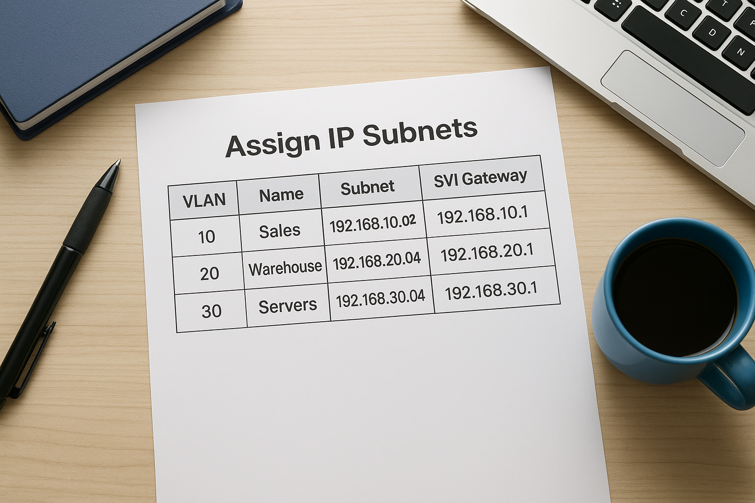
One subnet per VLAN with no overlap is a hard requirement. Overlapping subnets cause routing failures that are difficult to diagnose after the fact.
| VLAN | Name | Subnet | SVI Gateway |
|---|---|---|---|
| 10 | Sales | 192.168.10.0/24 | 192.168.10.1 |
| 20 | Warehouse | 192.168.20.0/24 | 192.168.20.1 |
| 30 | Servers | 192.168.30.0/24 | 192.168.30.1 |
This table becomes your reference throughout Steps 2 and 3.
Step 2. Create VLANs and assign switch ports
With your plan from Step 1 in hand, you can now build the VLAN structure on the switch. This step creates the logical VLAN entries and assigns physical ports to them, which is the foundation that makes inter VLAN routing on a Layer 3 switch functional in the next step.
Create VLANs in the VLAN Database
Enter global configuration mode and create each VLAN using its ID and a descriptive name. Naming every VLAN at creation keeps your configuration readable and reduces errors during future maintenance or audits.
Switch# configure terminal
Switch(config)# vlan 10
Switch(config-vlan)# name Sales
Switch(config-vlan)# exit
Switch(config)# vlan 20
Switch(config-vlan)# name Warehouse
Switch(config-vlan)# exit
Switch(config)# vlan 30
Switch(config-vlan)# name Servers
Switch(config-vlan)# exit
Run
show vlan briefafter this step to confirm all VLANs appear as active before you proceed.
Assign Access Ports to Each VLAN
Once the VLANs exist, assign the correct physical ports to each one using access mode. Access mode tells the switch that the port carries traffic for a single VLAN only, which is the correct setting for end-user devices and servers.
Switch(config)# interface range GigabitEthernet1/0/1 - 10
Switch(config-if-range)# switchport mode access
Switch(config-if-range)# switchport access vlan 10
Switch(config-if-range)# exit
Repeat this block for each VLAN, substituting the correct port range and VLAN ID from your planning table.
Step 3. Configure SVIs and enable IP routing
This is where inter VLAN routing on a Layer 3 switch actually comes to life. You create a Switched Virtual Interface for each VLAN, assign it the gateway IP from your planning table, and turn on the switch’s routing engine. Without these steps, VLANs remain isolated regardless of how cleanly you built them in Step 2.
Enable IP Routing on the Switch
Start with a single global command that activates Layer 3 forwarding between VLANs. Without it, the switch treats all interfaces as Layer 2 only, and your SVIs will have IP addresses but will not route traffic.
Switch(config)# ip routing
Run
show running-config | include ip routingafter this command to confirm it is present in the active configuration before moving forward.
Create SVIs for Each VLAN
An SVI is a virtual Layer 3 interface tied to a VLAN ID. You assign it the gateway address from your planning table, and every host on that VLAN points to that address as its default gateway. Create one SVI per VLAN using the same IDs you defined in Steps 1 and 2.
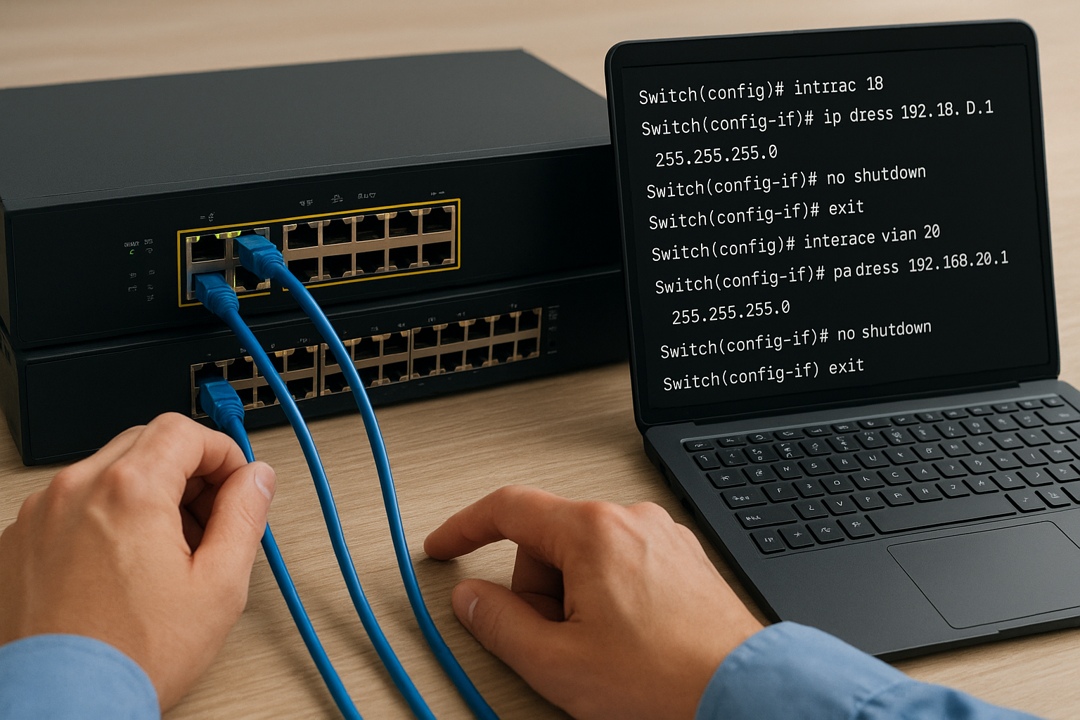
Switch(config)# interface vlan 10
Switch(config-if)# ip address 192.168.10.1 255.255.255.0
Switch(config-if)# no shutdown
Switch(config-if)# exit
Switch(config)# interface vlan 20
Switch(config-if)# ip address 192.168.20.1 255.255.255.0
Switch(config-if)# no shutdown
Switch(config-if)# exit
Switch(config)# interface vlan 30
Switch(config-if)# ip address 192.168.30.1 255.255.255.0
Switch(config-if)# no shutdown
Switch(config-if)# exit
Repeat this block for every VLAN in your plan, substituting the correct ID and subnet each time.
Step 4. Verify and troubleshoot inter-VLAN routing
Once your SVIs are up, you need to confirm that inter VLAN routing on a Layer 3 switch is actually forwarding traffic between segments. Do not assume it works because the configuration looks right. Run verification commands directly on the switch to check interface states and the routing table before you test from an end device.
Confirm Routing Is Working
Run these commands in privileged EXEC mode to validate your configuration:
Switch# show ip route
Switch# show interfaces vlan 10
Switch# show interfaces vlan 20
Switch# show interfaces vlan 30
Switch# ping 192.168.20.1 source vlan 10
The show ip route output should list connected routes for every SVI subnet you configured. Each show interfaces vlan output should read "line protocol is up." If an SVI shows "line protocol is down," that VLAN has no active access ports assigned to it, which means no physical port in that VLAN has a connected device.
An SVI stays down until at least one access port assigned to that VLAN comes up with a connected link.
Common Problems and Fixes
Most failures trace back to three causes. Use this table to diagnose quickly:
| Symptom | Likely Cause | Fix |
|---|---|---|
| SVI line protocol is down | No active port in the VLAN | Connect a device or check port assignment |
ip routing missing from config |
Command was never entered | Run ip routing in global config |
| Hosts cannot ping the gateway | Wrong default gateway on host | Set host gateway to match the SVI IP |
Wrap Up
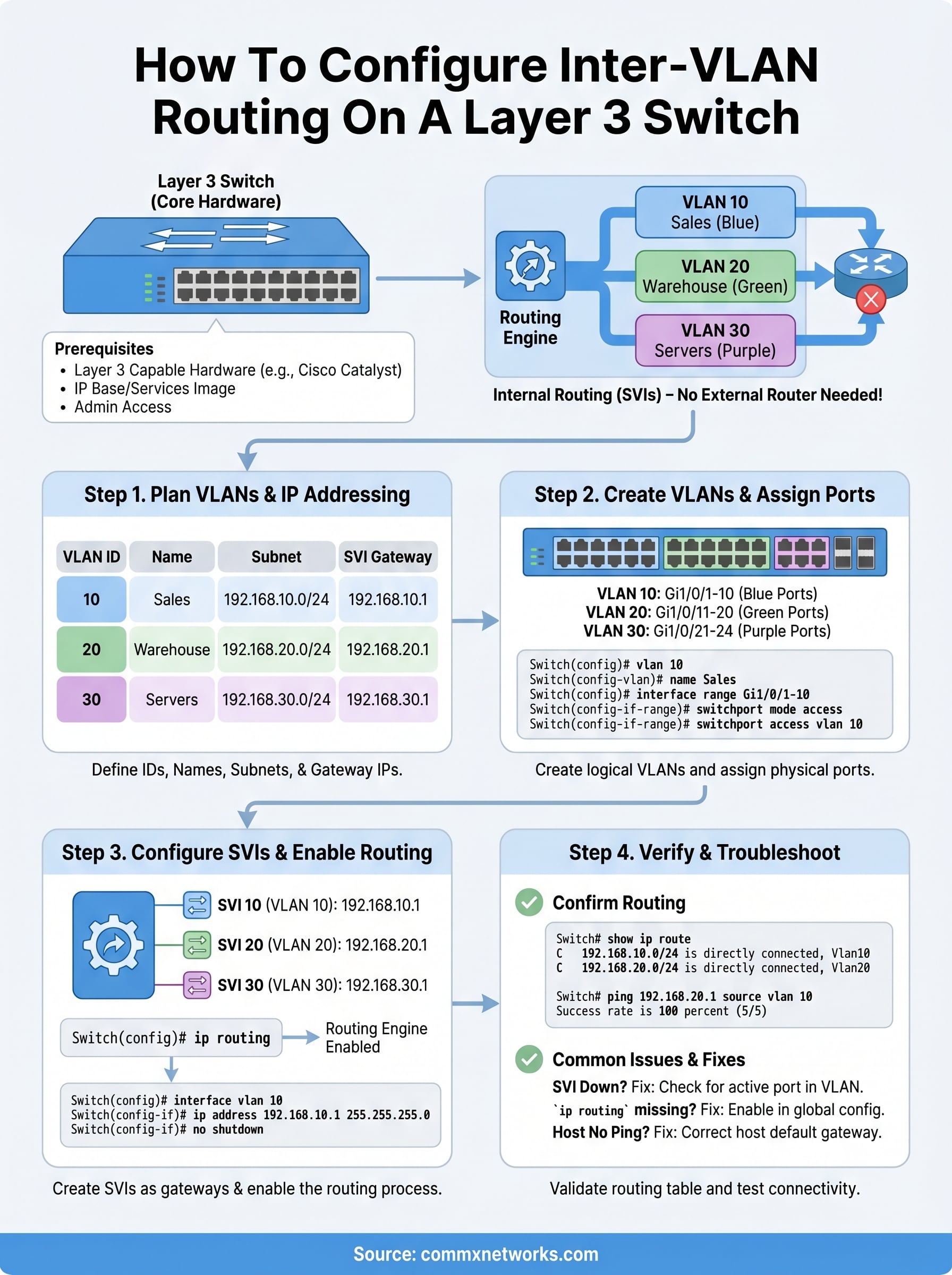
You now have everything you need to configure inter VLAN routing on a Layer 3 switch from start to finish. The process comes down to four repeatable steps: plan your VLANs and subnets, create the VLANs and assign access ports, configure SVIs with the correct gateway addresses and enable ip routing, then verify the routing table and test connectivity before you call it done. Skipping verification is where most deployments run into problems, so always confirm SVI states and connected routes before you hand the network off to end users.
Building a clean Layer 3 switching configuration depends on solid physical infrastructure underneath it. Properly terminated cabling, organized MDF and IDF setups, and correctly patched switch ports make the difference between a network that holds up under load and one that causes repeated troubleshooting calls. If you need help with the physical side of your network build, contact CommX Networks to get a professional assessment.