
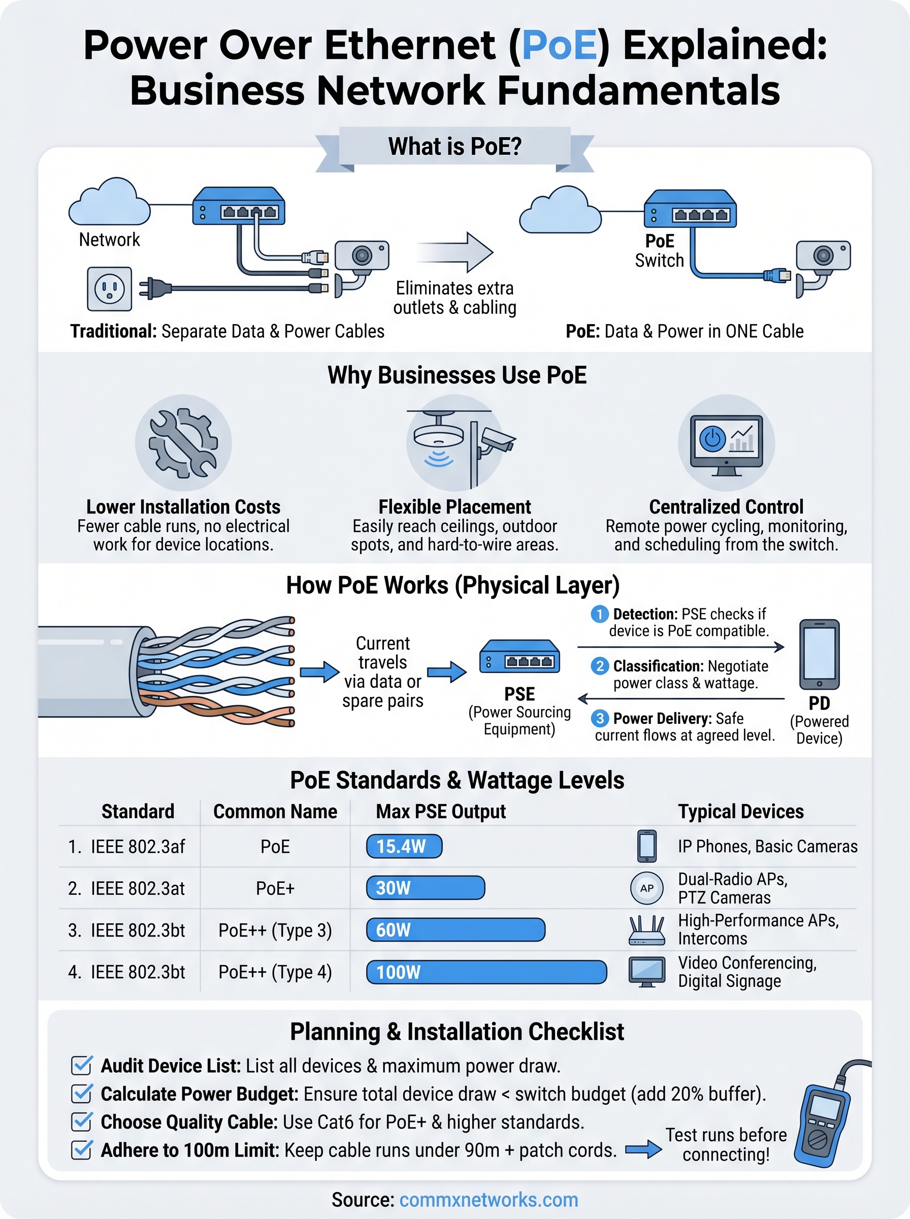
Every IP camera, wireless access point, and VoIP phone in your building needs two things: a network connection and power. Traditionally, that meant running both a data cable and an electrical line to each device, doubling the labor, cost, and complexity. Power over Ethernet explained simply: it’s a technology that delivers data and electrical power through a single Ethernet cable, eliminating the need for separate power sources at each device location.
For commercial facilities across Southwest Florida, PoE has become a foundational part of how network infrastructure gets built. At CommX Networks, we design and install the structured cabling systems that make PoE deployments work reliably at scale, whether that’s a warehouse full of security cameras or an office complex with dozens of wireless access points. The technology matters because it directly affects how much your infrastructure costs to install, expand, and maintain over time. Getting it right starts with understanding how it actually works.
This article breaks down PoE technology from the ground up: what it is, the standards behind it, the equipment involved, wattage limits, and how businesses use it in practice. By the end, you’ll have a clear picture of whether PoE fits your facility’s needs and what to consider before your next infrastructure project. We’ll also cover common mistakes and limitations so you can plan with full visibility, not assumptions.
What Power over Ethernet is and what it isn’t
Power over Ethernet is a networking standard that lets an Ethernet cable carry electrical current alongside data signals to a connected device. Instead of plugging a camera or access point into a separate wall outlet, the device draws the power it needs directly from the cable running to your network switch. That’s the core of it: one cable, two functions, delivered through the same copper wires you already use for data transmission.
The core definition of PoE
To understand power over ethernet explained in practical terms, think about what an Ethernet cable actually contains. A standard Cat5e or Cat6 cable holds eight copper conductors arranged in four twisted pairs. Data transmission uses a portion of those conductors, which leaves room for electrical current to travel alongside the signal. IEEE standards define exactly how that current gets applied, at what voltage, and how the switch and the end device negotiate the connection before power flows.
The device that receives power is called a powered device, or PD, which includes IP cameras, VoIP phones, and wireless access points. The device that supplies power is called power sourcing equipment, or PSE, which is typically a PoE-capable network switch or a standalone PoE injector. When a PD connects to a PSE, they run a brief handshake to confirm compatibility before any current moves through the cable. That negotiation step protects non-PoE equipment from receiving voltage it was never designed to handle.
What PoE does not do
PoE does not replace your building’s electrical infrastructure. It does not power desktop computers, large monitors, servers, or any device that draws more wattage than the applicable PoE standard allows. Treating PoE as a catch-all power delivery method for your facility leads to equipment damage, failed installations, and budget overruns on replacement hardware.
PoE is purpose-built for low-power networked devices, and working within that boundary is exactly what makes it reliable at commercial scale.
Your PoE switch itself still requires a standard electrical connection to your building’s power system. The total PoE power budget on that switch is one of the most frequently overlooked constraints in a commercial deployment. If a switch carries a 370-watt PoE budget and each connected device draws 30 watts, you can run roughly 12 devices before the switch starts throttling or cutting power to endpoints. Calculating that budget before you purchase equipment prevents the kind of mid-project redesign that costs far more than the planning would have.
Why businesses use PoE
The case for PoE in a commercial facility comes down to installation cost and placement flexibility. When you drop the requirement for a dedicated electrical outlet at every device location, you cut labor hours, eliminate extra conduit runs, and remove the need to coordinate electrical work separately from your network installation. For a facility with 40 cameras or 20 access points, those savings represent a meaningful reduction in total project cost.
Lower installation costs and simpler device placement
With power over ethernet explained in real deployment terms, the biggest advantage is where you can actually put devices. Ceiling-mounted access points and outdoor security cameras frequently sit in locations where running electrical conduit is expensive or structurally difficult. PoE lets you reach those spots with a single cable pull from your network closet, cutting both material and labor on every device run.
When placement decisions follow your network design instead of your outlet locations, you get infrastructure that fits your facility rather than works around it.
Removing the separate electrical run also simplifies your project timeline. Network cabling and power delivery get handled in a single scope of work, which reduces contractor coordination and lowers the risk of scheduling delays during a build-out or expansion.
Centralized power control and faster troubleshooting
A PoE switch gives your IT team remote power cycling without anyone walking to the device physically. When a camera locks up or an access point stops responding, you reboot it from the switch’s management interface in seconds. Centralized power monitoring also lets you track consumption across connected devices and flag unusual draws before they cause a failure.
Managed PoE switches also support scheduled power cycling, which helps automate routine maintenance across large device counts. For facilities running dozens of endpoints, that level of control reduces hands-on service calls and keeps downtime low.
How PoE works on an Ethernet cable
A standard Cat5e or Cat6 cable contains eight copper conductors arranged in four twisted pairs. Data transmission uses those pairs to carry differential signals, but the same conductors can also carry direct current without interfering with data. PoE takes advantage of that physical property to deliver electrical power from your switch to each connected device through the same cable run.
Understanding power over ethernet explained at the physical layer helps you verify that your cabling infrastructure can actually support the devices and standards you plan to deploy.
How current travels through the cable pairs
The IEEE 802.3 standard defines two methods for delivering power across Ethernet conductors. Alternative A applies current to the pairs that also carry data signals, while Alternative B uses the spare pairs that 100Mbps connections leave unused. Both methods protect signal integrity by using the balanced, differential nature of twisted-pair wiring.
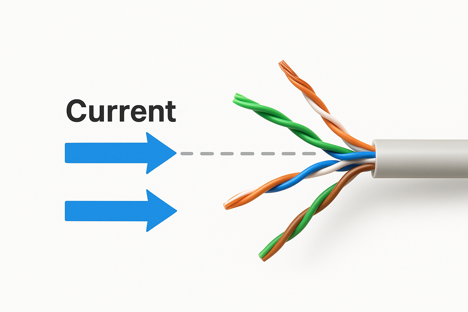
| Method | Pairs Used | Typical Application |
|---|---|---|
| Alternative A | Pairs 1-2, 3-6 | Data-active pairs |
| Alternative B | Pairs 4-5, 7-8 | Spare pairs on 100Mbps links |
The handshake between PSE and PD
Before any current flows, your switch runs a detection sequence to confirm the connected device is a legitimate powered device and not standard equipment that would be damaged by unexpected voltage on the cable. The PSE sends a low-voltage probe signal and reads the resistance response from the PD. If that resistance falls within the IEEE-defined range, the switch moves to the classification phase, where both sides agree on a power class and wattage level before current is released.
Once classification completes, power delivery begins at the negotiated wattage level and the device boots normally. If the detection step fails at any point, the switch holds the port at safe standby voltage and logs the event for your review.
PoE standards, power levels, and device types
The IEEE has defined several PoE standards over time, and each standard sets a maximum wattage that the PSE can deliver to a connected PD. Choosing the wrong standard for your devices means either underpowering hardware or overspending on switch infrastructure. With power over ethernet explained at the standards level, you can match your switch purchases to the actual devices your facility runs.
IEEE standards and wattage levels
IEEE 802.3af was the original PoE standard, delivering up to 15.4 watts per port at the PSE and guaranteeing at least 12.95 watts at the device after cable loss. IEEE 802.3at, known as PoE+, raised that ceiling to 30 watts per port, which covers most modern IP cameras and dual-radio access points. The newer IEEE 802.3bt standard adds two higher tiers: Type 3 at 60 watts and Type 4 at 100 watts, covering more demanding devices like video conferencing endpoints and high-density access points.
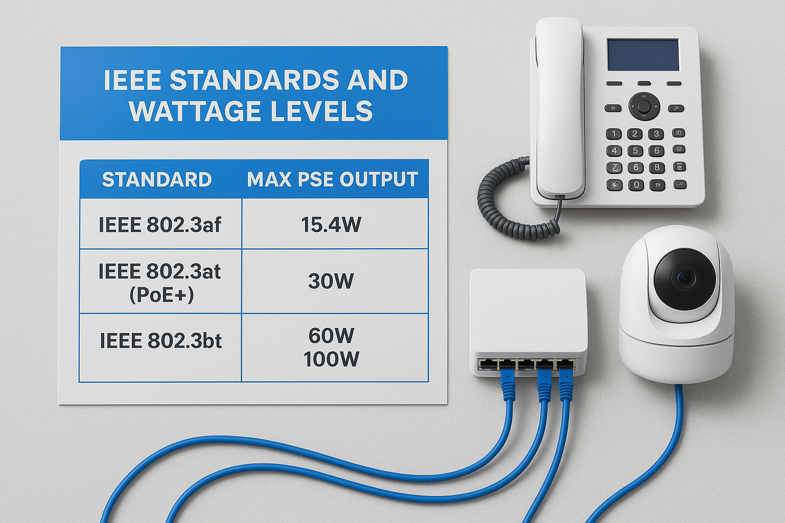
Selecting a switch before you know the power class of every device you plan to connect is one of the most common causes of mid-project budget overruns.
| Standard | Max PSE Output | Typical Devices |
|---|---|---|
| IEEE 802.3af | 15.4W | Basic IP cameras, VoIP phones |
| IEEE 802.3at (PoE+) | 30W | Dual-radio APs, PTZ cameras |
| IEEE 802.3bt Type 3 | 60W | High-performance APs, intercoms |
| IEEE 802.3bt Type 4 | 100W | Video conferencing, digital signage |
Matching the standard to your device type
Every powered device ships with a listed power draw, and that number tells you which standard your switch must support on that port. A basic VoIP phone pulling 5 watts runs fine on an 802.3af port, while a dual-radio wireless access point pushing 5GHz and 6GHz simultaneously may require 802.3at or higher. Confirm those specs before you finalize your switch order.
Common device categories by power class:
- 802.3af: IP desk phones, entry-level cameras, simple sensors
- 802.3at: Dual-band access points, PTZ cameras, door access controllers
- 802.3bt: High-density APs, video conferencing hardware, digital signage displays
How to plan and install PoE in a facility
Planning a PoE deployment starts before you touch a single cable. Your device list and switch selection drive every other decision in the project, so locking those in early prevents costly rework later.
Audit your device list and power budget first
Before you order a switch, list every device you plan to connect and note the maximum wattage draw for each one. Add those numbers together and compare the total against the PoE power budget listed on each switch you’re evaluating. A switch rated at 370 watts total capacity and 30 watts per port will not support 15 devices drawing 25 watts each without hitting budget limits. Build in a 20 percent overhead buffer so you have room to add devices later without replacing your switch.
Skipping the power budget calculation is the most common reason commercial PoE deployments require unplanned switch upgrades within the first year.
Cable quality and run length requirements
With power over ethernet explained at the physical layer in mind, your cabling choices directly affect how much power reaches each device. Cat5e and Cat6 both support PoE, but Cat6 carries higher-wattage standards more efficiently because its lower resistance reduces heat buildup and power loss across longer runs. IEEE standards cap the maximum cable run at 100 meters (328 feet) from switch to device, and power loss increases as you approach that limit.
Keep these points in mind during installation:
- Use Cat6 cabling for any PoE+ or PoE++ deployments
- Keep cable runs below 90 meters to leave room for patch cables at each end
- Test every run with a cable certifier before connecting devices to confirm it meets IEEE 802.3 specifications
Next steps for your network
With power over ethernet explained from standard to installation, the next step is applying that knowledge to your specific facility. Your device list, cable runs, and switch selection all interact, and getting one wrong creates problems that surface mid-project when fixing them is most expensive. Start with your device inventory, confirm the power draw for each unit, calculate your total switch budget, and build in overhead before you purchase any hardware.
If your facility is in Southwest Florida and you’re planning a new build-out, an office expansion, or an infrastructure upgrade, working with an experienced contractor makes a measurable difference in how the project runs. CommX Networks designs and installs structured cabling and PoE infrastructure for commercial facilities across Fort Myers, Cape Coral, and Naples. Your project plan should be clear before work begins, not after. Contact the CommX Networks team to walk through your requirements and get a scoped plan for your next deployment.