
Knowing how to terminate fiber optic cable is one of those skills that separates a clean, reliable network installation from one that causes headaches for years. Whether you’re connecting runs to patch panels, linking switches between floors, or extending fiber to a new building on your property, the termination is where precision matters most. A poor connection means signal loss, intermittent drops, and troubleshooting nightmares that eat into your uptime and your budget.
At CommX Networks, we’ve spent over 18 years installing and terminating fiber optic cabling in commercial facilities across Southwest Florida, warehouses, office complexes, distribution centers, and everything in between. We’ve worked with every common connector type and termination method, and we know exactly where things go wrong when proper technique isn’t followed. That hands-on experience is what drives this guide.
Below, we break down the two primary methods for terminating fiber optic cable: mechanical (connectorized) termination and fusion splicing. You’ll learn what tools each method requires, the step-by-step process for both single-mode and multimode fiber, and the common mistakes that lead to failed connections. We also cover when it makes sense to handle termination yourself and when calling in a professional crew is the smarter move. By the end, you’ll have a clear, practical understanding of what the job involves from start to finish.
What fiber termination is and when you need it
Fiber optic cable carries data as pulses of light through a thin glass or plastic core. On its own, raw fiber is just a strand. To connect it to any equipment, whether a patch panel, a transceiver, or a managed switch, you need to attach a precisely fitted connector to the end of that fiber. That process is called fiber termination. Done correctly, it presents a clean, flat fiber endface that transmits light with minimal signal loss. Done poorly, it creates a gap, a crack, or a misaligned core that scatters light and kills network performance.
Termination quality directly controls how much signal makes it from one end of your fiber run to the other. Even a microscopic imperfection at the endface can add enough loss to fail an entire link.
What the termination process actually does
Every fiber termination shares the same goal: align the fiber core precisely inside a connector ferrule so that light passes straight through with minimal disruption. The ferrule, typically ceramic or stainless steel, holds the fiber in a fixed, repeatable position and provides the mechanical interface that plugs into equipment ports and adapter sleeves. When you learn how to terminate fiber optic cable properly, you’re learning how to prepare the fiber end, seat it correctly inside that ferrule, and verify that the finished joint meets the loss and reflectance specs your network requires.
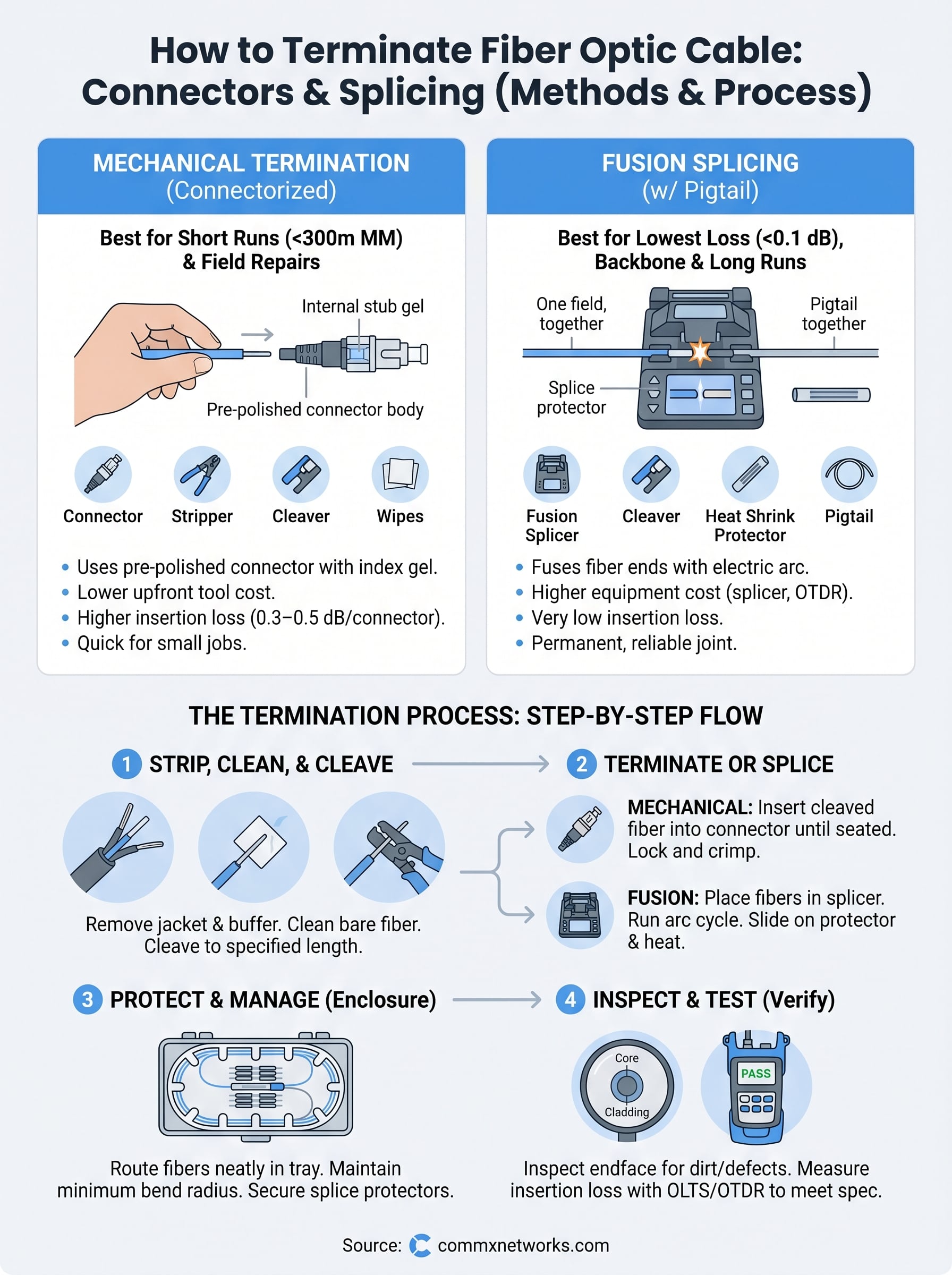
Two main approaches exist for reaching that goal. Mechanical connectorization uses a pre-polished connector with an internal alignment mechanism that grips the prepared fiber end directly in the field, no polishing wheel required. Fusion splicing with a pigtail uses an electric arc to fuse two fiber ends together, joining a pre-terminated pigtail to your field cable so that only factory-polished endfaces ever contact your equipment. Both approaches produce a working connection, but they differ meaningfully in cost, equipment requirements, and achievable insertion loss.
When you need to terminate fiber on a job
You need fiber termination any time a fiber run ends at a point where equipment must connect to it. The most common situation on commercial sites is new construction, where fiber is pulled through conduit and left with bare ends that need connectors at both the equipment rack and the work area outlet. You also encounter termination work during building expansions where you’re extending an existing backbone to a new wing, and during equipment upgrades where you’re replacing switches or adding transceivers that require a clean, low-loss fiber connection to function reliably.
Here are the specific scenarios where termination work comes up most often on commercial projects:
- New structured cabling installations where fiber runs are pulled and left with bare ends waiting for connectors at both ends
- Fiber repair jobs where a damaged cable section gets cut out and each new end requires a fresh termination
- Equipment room buildouts where fiber pigtails are spliced to the building backbone and dressed into an enclosure or patch panel
- Campus or multi-building links where outdoor fiber enters a building and transitions to indoor connectorized runs at the demarcation point
- Moves, adds, and changes where an existing run is rerouted or extended and one or both ends need new connectors installed
Knowing which scenario applies to your project and which termination method matches your environment determines the tools, time, and budget you’ll need before you pull a single foot of cable.
Tools and supplies you need before you start
Before you touch a single fiber strand, you need the right equipment on hand. Attempting to learn how to terminate fiber optic cable with the wrong tools leads to damaged fiber, failed inspections, and wasted connectors. The tools split into two groups depending on which method you use, and the investment between mechanical termination and fusion splicing differs significantly. Both methods share a core set of fiber prep and safety supplies, but the specialized equipment for each method is distinct.
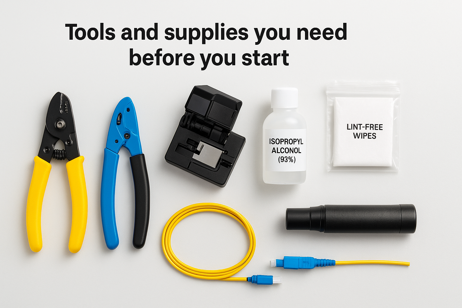
Cutting corners on fiber prep tools is the single most common reason commercial terminations fail visual inspection. A proper cleave starts with a proper cleaving tool, not a substitute.
Mechanical termination toolkit
Mechanical termination requires less capital investment than fusion splicing, but you still need precision instruments for prep work. The fiber prep steps involve stripping, cleaning, and cleaving before the connector ever touches the fiber, and each step needs a dedicated tool to do it correctly. Using the wrong stripper damages the buffer coating and leaves micro-cracks that cause insertion loss downstream.
Here are the tools and supplies you need for mechanical field connector termination:
| Tool / Supply | Purpose |
|---|---|
| Jacket stripper | Removes the outer cable jacket without nicking buffer tubes |
| Buffer tube stripper | Strips the 250 µm or 900 µm coating off the glass fiber |
| Precision fiber cleaver | Creates a flat, perpendicular endface on the bare fiber |
| Isopropyl alcohol (99%) | Cleans the bare fiber before insertion into the connector |
| Lint-free wipes | Wipes fiber clean without leaving residue or lint |
| Mechanical field connectors | Pre-polished connectors with internal index-matching gel |
| Fiber optic inspection scope | Verifies the endface before and after connector seating |
| Optical loss test set (OLTS) | Measures insertion loss across the finished termination |
Fusion splicing toolkit
Fusion splicing involves higher upfront equipment costs but consistently produces lower insertion loss than mechanical connectors, which is why it’s the standard choice for backbone and long-haul runs. The core piece of equipment is the fusion splicer itself, which uses an electric arc to melt two fiber ends together with micrometer-level precision. Alongside the splicer, you need heat shrink splice protectors, a cleaver capable of consistent 0.5-degree or better cleave angles, and an optical time-domain reflectometer (OTDR) to verify splice quality and locate any reflections along the full cable run. You also need the same jacket strippers, buffer strippers, alcohol, and lint-free wipes used in mechanical termination, since fiber prep steps are identical regardless of method.
Choose the right termination method
Before you buy connectors or rent a splicer, you need to pick the right termination method for your specific project. The decision comes down to three factors: the length of your fiber run, the loss budget your network equipment requires, and what tools you have access to in the field. Choosing the wrong method doesn’t just cost you money upfront. It can produce a termination that passes initial testing but degrades under real operating conditions or fails to meet the spec your equipment demands.
When to use mechanical field connectors
Mechanical field connectors are the right choice when you’re working on shorter runs inside a building, typically multimode runs under 300 meters, where the additional insertion loss of 0.3 to 0.5 dB per connector still falls within your link budget. They’re also the practical call when you need to terminate fiber quickly in the field without access to a fusion splicer, or when the volume of terminations on the job doesn’t justify renting splicing equipment. Most multimode office installations, data closet patch connections, and short horizontal runs land solidly in this category.
Mechanical connectors suit short-run multimode applications well, but avoid them on single-mode backbone links where loss budgets are tight and every tenth of a dB affects link reliability.
Use mechanical field connectors when your project meets these conditions:
- Multimode fiber (OM3, OM4) on runs under 300 meters
- Single-mode runs under 100 meters with equipment that carries a generous loss budget
- Field repairs where speed matters more than achieving the lowest possible loss
- Low-volume termination jobs where renting a fusion splicer is not cost-effective
When to choose fusion splicing
Fusion splicing is the correct method whenever you need the lowest possible insertion loss on a link, typically 0.02 to 0.1 dB per splice, which matters most on single-mode backbone runs, long campus links, and applications where your transceivers have tight receive power requirements. It’s also the right call when you’re learning how to terminate fiber optic cable for long-haul installations where mechanical connector loss would stack across multiple connection points and push you outside your loss budget. The higher equipment cost pays for itself quickly on large commercial jobs with many splice points across multiple floors or buildings.
Choose fusion splicing when your project involves:
- Single-mode fiber on any run longer than 100 meters
- Backbone links between IDFs and MDFs in multi-floor buildings
- Campus or inter-building runs where cumulative insertion loss is a concern
- High-density splice enclosures where consistency across many terminations is critical
Set up a clean, safe work area
Your work environment directly affects whether your terminations pass inspection on the first attempt. Fiber prep generates microscopic glass shards and dust particles that contaminate connector ferrules, scratch fiber endfaces, and create the exact defects you’re trying to avoid. Before you learn how to terminate fiber optic cable in a controlled setting, you need to build that controlled setting first. A cluttered, poorly lit workspace turns a straightforward procedure into a frustrating one.
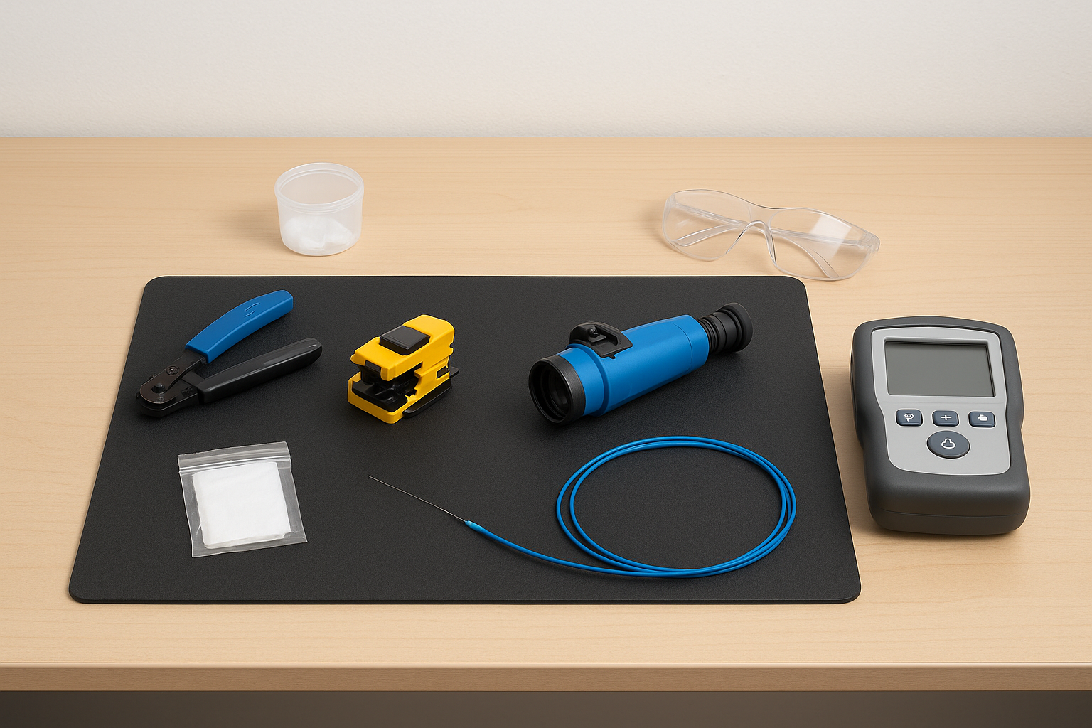
A single piece of dust on an endface can cause enough insertion loss to fail a link test, so treating your work area like a clean room is not optional.
Control dust and debris
Choose a stable, flat work surface away from HVAC vents, open doors, and any equipment that generates airflow. Even a mild breeze carries particles onto exposed fiber ends and freshly opened connector ferrules. Lay down a dark-colored, lint-free mat on your work surface so you can see bare fiber strands clearly against the background. Light-colored surfaces hide glass fragments and increase the risk of contamination and failed terminations.
Keep your workspace organized with a clear layout:
- Place your stripper, cleaver, and alcohol wipes on the left side in the order you’ll use them
- Keep a sealed container nearby for disposing of cleaved fiber ends immediately after each cut
- Store unused connectors in their original packaging until the moment you need them
- Position your inspection scope and test equipment on the right side, away from prep tools
Never blow on fiber ends or wave them near exposed surfaces. Use lint-free wipes with 99% isopropyl alcohol for every clean step, and discard each wipe after a single use.
Protect yourself during fiber work
Bare glass fiber strands are invisible to the naked eye and sharp enough to embed in skin or eyes without you noticing immediately. Before you start any prep work, put on safety glasses rated for fiber work and close-toe shoes. Keep a pair of tweezers on your work surface for handling cleaved ends, and never dispose of fiber scraps loosely in a trash can where someone can reach in and injure themselves.
Work in adequate lighting at all times. A task light positioned directly over your work mat lets you see the fiber strand clearly during stripping and cleaving, which directly reduces the chance of a bad prep that ruins an expensive connector.
Step 1. Strip, clean, and cleave the fiber
Fiber prep is the foundation of every successful termination, and this first step is where most beginners make mistakes that cost them connectors and test failures later. When you learn how to terminate fiber optic cable, you quickly realize that a bad strip or a poor cleave contaminates the connector ferrule before you even assemble it. Precision at this stage determines whether your termination passes inspection on the first attempt or gets rejected and reworked.
Strip the jacket and buffer coating
Start by removing the outer cable jacket using a jacket stripper rated for the cable diameter you’re working with. Hold the cable firmly, position the stripper 40 to 50 mm back from the end, and pull toward the tip with steady, even pressure. Avoid rotating the stripper aggressively, since that scores the buffer tubes underneath. Once the jacket is off, locate the bare fiber strands inside and remove any aramid (Kevlar) strength members by cutting them flush with scissors.
Next, strip the 250 µm or 900 µm coating from the bare glass fiber using a dedicated buffer tube stripper. Position the stripper jaws at the distance your connector manufacturer specifies, typically 25 to 30 mm from the fiber tip, and pull in a single smooth motion away from the cable.
A jerky or repeated stripping motion leaves micro-cracks in the glass that no cleave can fix, so strip each fiber in one controlled pull.
Here is a quick reference for strip lengths by connector type:
| Connector Type | Jacket Strip Length | Buffer Strip Length |
|---|---|---|
| LC (mechanical) | 40 mm | 25 mm |
| SC (mechanical) | 50 mm | 30 mm |
| Fusion pigtail prep | 60 mm | 30 mm |
Clean the bare fiber
After stripping, the bare glass carries residual coating fragments and contamination that must come off before you cleave. Fold a lint-free wipe, apply a few drops of 99% isopropyl alcohol, and wipe the exposed fiber from the stripped end toward the jacket in a single pass. Use a fresh section of the wipe for each fiber strand. Never go back and forth; one direction only, one wipe per pass.
Cleave to the correct length
Set your precision fiber cleaver to the strip length specified by your connector manufacturer and place the fiber in the guide groove. Close the clamping mechanism, apply the scribing blade, and release the fiber in one motion. Inspect the cleaved end under your fiber scope immediately. A good cleave shows a flat, perpendicular endface with no hackles, chips, or lip. Any defect means you strip back and cleave again before proceeding.
Step 2. Terminate with a mechanical field connector
With your fiber stripped, cleaned, and cleaved to the correct length, you’re ready to install the connector. Mechanical field connectors use a pre-polished ferrule stub and an internal index-matching gel to bridge the gap between your cleaved fiber end and the factory-polished surface inside the connector. Understanding how to terminate fiber optic cable with this method requires you to handle the connector carefully once opened, since any contamination introduced at this stage puts gel on the endface and causes inspection failure.
Load the fiber into the connector
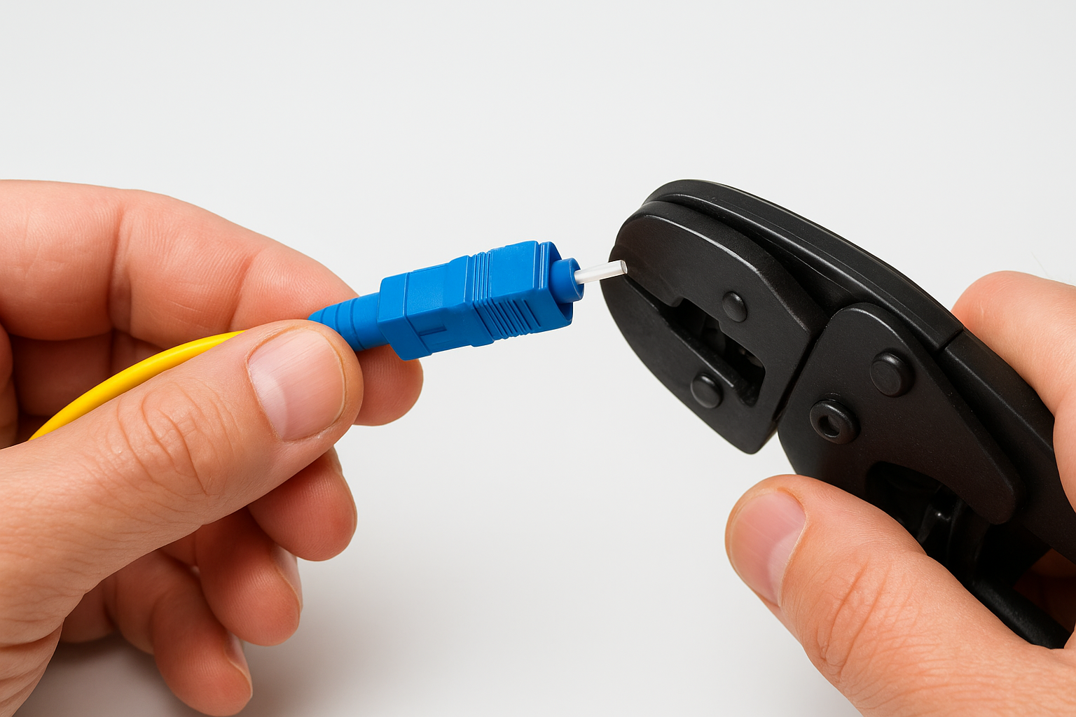
Open the connector packaging immediately before use and hold it by the body, never by the ferrule tip. Slide the connector boot and strain relief sleeve onto your cable before you insert the fiber, since these components must be in place before the connector body is crimped. With the boot positioned back on the cable, insert the cleaved fiber end straight into the connector’s rear entry port, using slow, steady forward pressure until you feel the fiber make contact with the internal pre-polished stub.
The moment you feel resistance, stop pushing. Forcing the fiber past the contact point chips the internal stub and creates an endface defect that no amount of retesting will fix.
Most mechanical connector bodies include a locking tab or cam mechanism that you press down to clamp the fiber in place once it seats correctly. Follow the connector manufacturer’s specific locking sequence for the model you’re using. The table below shows the insertion depth and locking action for two common mechanical connector types:
| Connector Type | Insertion Depth | Locking Action |
|---|---|---|
| LC mechanical (e.g., UniCam style) | Until resistance is felt at stub | Press top tab flush with body |
| SC mechanical (e.g., UniCam style) | Until resistance is felt at stub | Slide latch forward until it clicks |
Secure and verify the termination
After locking the fiber, slide the strain relief boot forward over the connector body and crimp the rear of the connector onto the cable using a fiber optic crimp tool. Apply firm, even pressure in a single stroke to seat the crimp ring without twisting the cable. Inspect the ferrule endface immediately using your fiber inspection scope before you install the connector into any adapter or patch panel port.
A passing endface shows no cracks, chips, or gel contamination in the core zone or cladding zone. If your scope reveals any defect, remove the connector, cut back the cable to expose fresh fiber, and repeat the prep and insertion steps rather than proceeding with a failed termination.
Step 3. Fusion splice a pigtail and add a connector
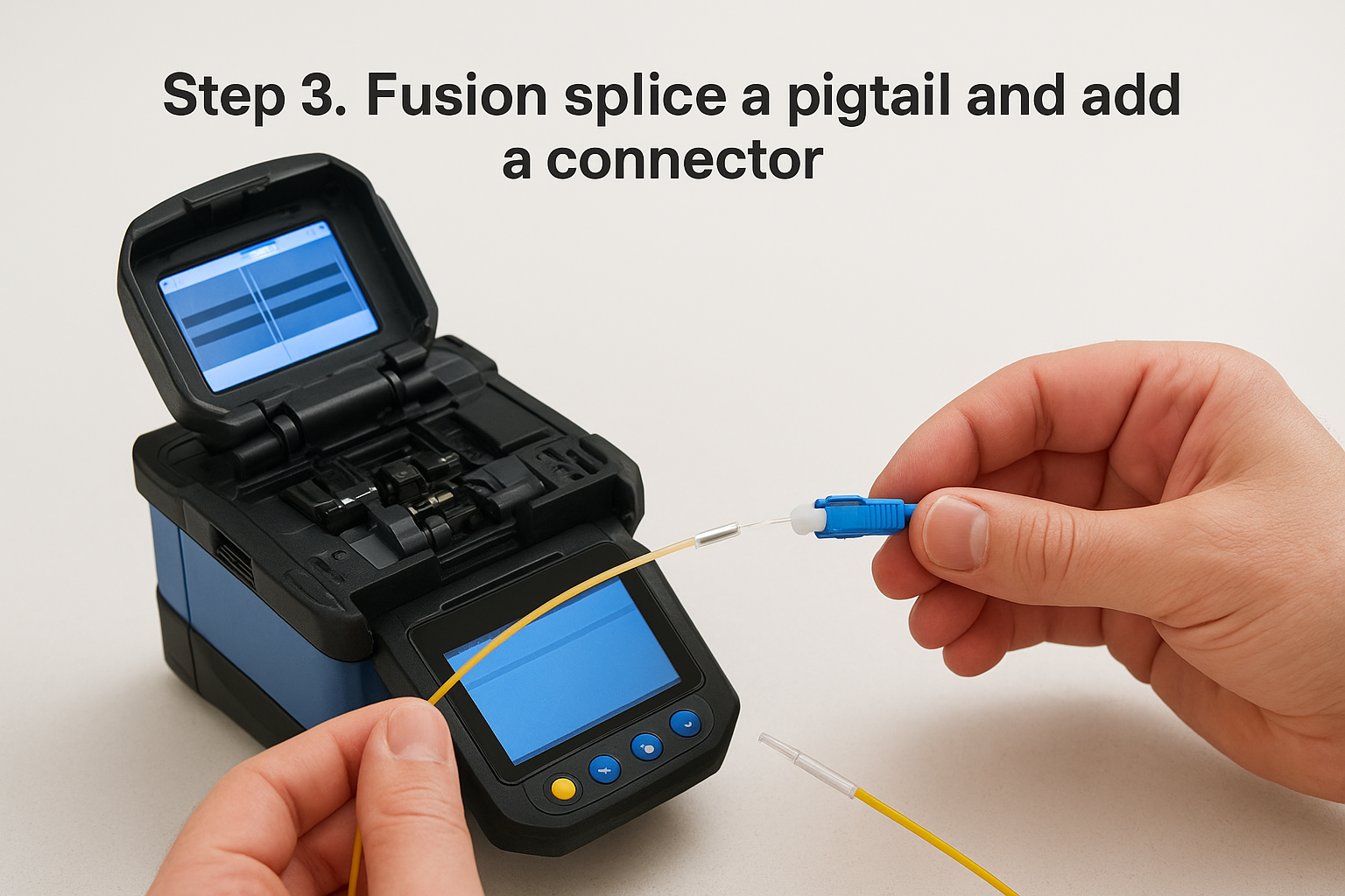
Fusion splicing is how you achieve the lowest insertion loss of any field termination method, typically between 0.02 and 0.1 dB per splice. Instead of inserting raw field fiber into a connector ferrule, you fuse your field cable end to a pre-terminated pigtail, a short length of fiber with a factory-polished connector already attached. Your equipment only ever sees the factory endface, not anything you prepared in the field. To understand how to terminate fiber optic cable at this level, you need a fusion splicer, a precision cleaver, and heat shrink splice protectors before you start.
Prepare the pigtail and field fiber
Strip and clean both the field fiber and the pigtail fiber using the same technique from Step 1. Strip the buffer coating back 30 mm on each end, wipe both bare strands with 99% isopropyl alcohol and a fresh lint-free wipe, then cleave each one using your precision cleaver. Before placing either fiber in the splicer, slide a heat shrink splice protector onto the field cable, because once the splice is made, you cannot add it.
Cleave both fibers within 60 seconds of cleaning to avoid surface contamination that the splicer’s arc cannot correct.
Place each cleaved fiber into the splicer’s V-groove holders with the ends facing each other across the arc gap. Check the splicer’s real-time endface inspection screen to confirm both fibers are seated properly in the grooves and that neither endface shows chips or hackles. Most commercial fusion splicers display both endfaces simultaneously before committing to the splice cycle.
Run the splice cycle and protect the joint
Close the splicer lid and press the splice button. The splicer performs an automatic arc calibration, aligns the two fiber cores using active core alignment, then fires the arc to fuse the ends together. The whole process takes roughly 10 to 15 seconds on a modern unit. When the cycle completes, read the estimated splice loss displayed on the screen. Any result above 0.1 dB on single-mode fiber warrants a re-splice rather than proceeding.
Once you accept the splice result, slide the heat shrink protector over the exposed splice joint, centering it over the fused point. Place the protector in the splicer’s heating sleeve, close the heater, and let the unit complete its shrink cycle, typically 30 to 40 seconds. After the protector cools, flex it gently to confirm it is rigid and fully sealed around the joint before moving the cable.
Step 4. Protect and manage fibers in an enclosure
Once your splices and connectors are finished, the fibers are still vulnerable until you seat them properly inside a fiber enclosure or splice tray. This step is where a lot of installers rush and pay for it later: a pinched fiber, a tight bend radius violation, or a loose splice protector all cause signal loss that shows up the first time someone opens the enclosure to add a run or troubleshoot a link. Managing fibers correctly inside an enclosure is a core part of how to terminate fiber optic cable the right way from end to end.
Route fibers within the minimum bend radius
Every fiber type has a minimum bend radius that you must maintain throughout the enclosure, both during installation and at rest. Violating the bend radius compresses the fiber core, increases attenuation, and can cause stress fractures over time. For standard single-mode and multimode fiber, the minimum long-term bend radius is 10 times the cable outer diameter, which works out to roughly 30 mm for most 3 mm jacketed pigtails. During routing, the installation bend radius is typically 20 times the outer diameter, so give your fingers more room to work than you think you need.
Bend radius violations are invisible during initial testing because signal loss from a pinch can fall just within spec, then drift out of tolerance as the fiber settles under mechanical stress over weeks or months.
Check every routing path before you close the tray. If any fiber arc looks tighter than your minimum threshold, re-route that strand before moving on.
Seat splice protectors and dress pigtails into trays
Fusion splice protectors must sit flat in the splice holder slots inside the tray, with the shrunk tube fully supported along its length. Drop each protector into its slot with the fused point centered under the retention clip, then press the clip down until it snaps. Pigtails from the splices route through the fiber management guides built into the tray perimeter, looping gently to absorb any slack without stacking fibers on top of each other.
Use the following checklist before closing each tray:
- All splice protectors seated flat and clipped down
- No fiber crossovers inside the tray routing channels
- Slack coiled in the designated loop storage area, not bunched loosely
- Connectorized pigtail ends routed cleanly out of the tray and toward the patch panel ports
- Tray secured with its retention screws or latches before moving to the next one
Step 5. Inspect and test for loss and reflectance
Testing is not an optional final step you skip when the schedule is tight. It is the only way to confirm that every termination you’ve completed actually performs within spec before your client connects equipment to the network. Learning how to terminate fiber optic cable correctly includes knowing how to verify your work, and that verification requires two distinct tools: a fiber inspection scope for endface quality and an optical loss test set (OLTS) for measuring actual signal loss across each completed link.
Inspect each endface before connecting to equipment
Inspect every connector endface with a fiber inspection scope before you plug it into any adapter, patch panel, or transceiver port. A dirty or damaged endface transfers contamination directly to the port it contacts, and cleaning a port is significantly harder than cleaning a connector. Position the scope over the ferrule tip and check the endface under at least 200x magnification. A clean, passing endface shows no scratches in the core zone, no pits or chips in the cladding, and no contamination in the contact zone.
Any scratch that crosses the core zone means you need to clean and re-inspect before connecting, not after.
Use the IEC 61300-3-35 standard zones as your pass/fail reference when evaluating endfaces:
| Zone | Radius | Defect Limit |
|---|---|---|
| Core | 0 to 25 µm | No scratches, no contamination |
| Cladding | 25 to 120 µm | No pits, scratches under 2 µm wide |
| Contact | 120 to 250 µm | Minor contamination allowed |
| Adhesive | 250 µm and beyond | No restrictions |
Run an insertion loss test with an OLTS
Connect your optical loss test set using a calibrated test reference cord and measure the insertion loss for each fiber link end to end. Record every result and compare it against your project’s link loss budget. For a typical multimode OM4 link with two mechanical connector terminations, you should see total connector loss under 0.75 dB combined. Single-mode links with fusion splices should show connector plus splice loss well under 0.5 dB across the full run.
Capture results in a test report that includes the fiber ID, measured loss, pass/fail status, and the test equipment serial number and calibration date. This documented test record protects you if a link issue surfaces later and gives your client a clear baseline for future troubleshooting.
Verify splice integrity with an OTDR
Run an OTDR trace on any link that includes fusion splices to confirm each splice point registers below 0.1 dB and that no reflections appear at unexpected locations along the run. The OTDR sends a light pulse down the fiber and displays a distance-versus-loss graph that shows every connector, splice, and bend event as a visible marker on the trace. Save each OTDR trace file alongside your OLTS records as part of your complete link documentation package.
Wrap it up and avoid rework
Every stage of how to terminate fiber optic cable builds on the one before it. A clean strip feeds a good cleave, a good cleave feeds a clean endface, and a clean endface is what keeps your termination out of the rework pile. The steps in this guide give you a repeatable process you can run on every connector and every splice, whether you’re working on a single-floor office buildout or a multi-building campus link. Follow the testing sequence at the end, document your results, and you hand your client a verified, spec-compliant installation instead of a promise.
When the job is large, the loss budget is tight, or your team lacks access to a fusion splicer and OTDR, bringing in an experienced crew is the faster and more reliable path. If you’re based in Southwest Florida and need commercial fiber termination done right the first time, contact CommX Networks to discuss your project.