
Before you mount a single access point or run a cable, you need a plan. The Ubiquiti Design Center is a free, browser-based tool that lets you map out WiFi coverage and security camera placements on your actual floor plan, before any hardware ships or any holes get drilled. It’s one of the most practical planning tools available for commercial network and surveillance projects.
At CommX Networks, we use this tool regularly when designing network infrastructure and camera systems for warehouses, office buildings, and large commercial spaces across Southwest Florida. It helps us show clients exactly what their coverage will look like and where gaps might exist. Whether you’re working with an integrator like us or planning a deployment on your own, understanding how Design Center works gives you a serious advantage.
This guide walks you through the tool step by step, from importing a floor plan to placing devices, adjusting coverage zones, and exporting a finished design you can actually build from.
What Ubiquiti Design Center does and what you need
The Ubiquiti Design Center is a browser-based planning tool that lets you simulate WiFi coverage and camera field-of-view on a real floor plan before you buy or install anything. You upload your building layout, drop in UniFi access points or cameras, and the tool renders signal heatmaps and coverage zones in real time. It’s purpose-built for UniFi hardware, so every device in the library reflects actual product specs, not generic estimates.
Simulating your layout before installation is the fastest way to catch coverage gaps, over-provisioning, and budget problems before they become job-site headaches.
What the tool covers
Two main planning workflows live inside the design center: wireless network coverage and security camera placement. On the WiFi side, you can test different access point models, adjust transmit power settings, and see how walls, floors, and obstacles affect signal strength across your space. On the camera side, you set field-of-view angles, lens types, and mounting heights to confirm you’re covering every critical zone before you commit to a bracket location. Both workflows update visually as you move devices around, which makes it easy to compare options quickly.
What you need before you start
You don’t need an account to explore the tool, but signing in with a free Ubiquiti account saves your projects and lets you share them with contractors, clients, or your IT team. Beyond the login, gather two things before you open a new project:
- A floor plan image (PNG, JPG, or PDF) with at least one known measurement you can use to calibrate the scale
- A working list of the UniFi devices you plan to test, such as specific AP models or camera types you’re considering for the project
If you don’t have an architectural CAD file, a scanned hand sketch or a photograph of a printed floor plan works for early-stage planning. The key is getting the proportions accurate enough that the coverage simulation reflects real-world conditions in your building.
Step 1. Create a project and add your floor plan
Open the Ubiquiti Design Center at design.ui.com and log in with your Ubiquiti account. Click "New Project" from the dashboard and give it a descriptive name, like "Fort Myers Warehouse Phase 1." Clear naming helps when you manage multiple sites or building phases at the same time.
Upload your floor plan image
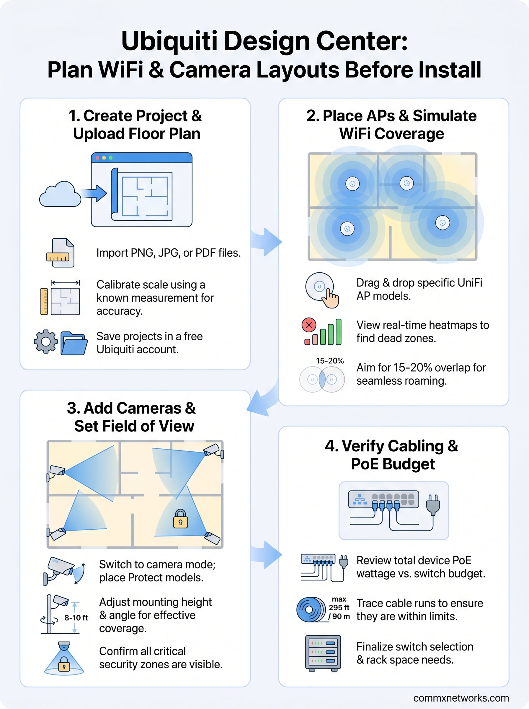
Click the floor plan import button inside your new project and upload a PNG, JPG, or PDF file. The tool supports multi-page PDFs, so you can add each floor as a separate level within the same project, keeping everything organized in one place.
Calibrate your floor plan immediately after upload. If the scale is off, every coverage estimate the tool generates will be wrong.
Set the scale correctly
Use the scale calibration tool to draw a line across a known dimension, such as an exterior wall or corridor with a confirmed measurement. Enter the real-world distance in feet or meters and the tool locks in the ratio for the entire floor plan.
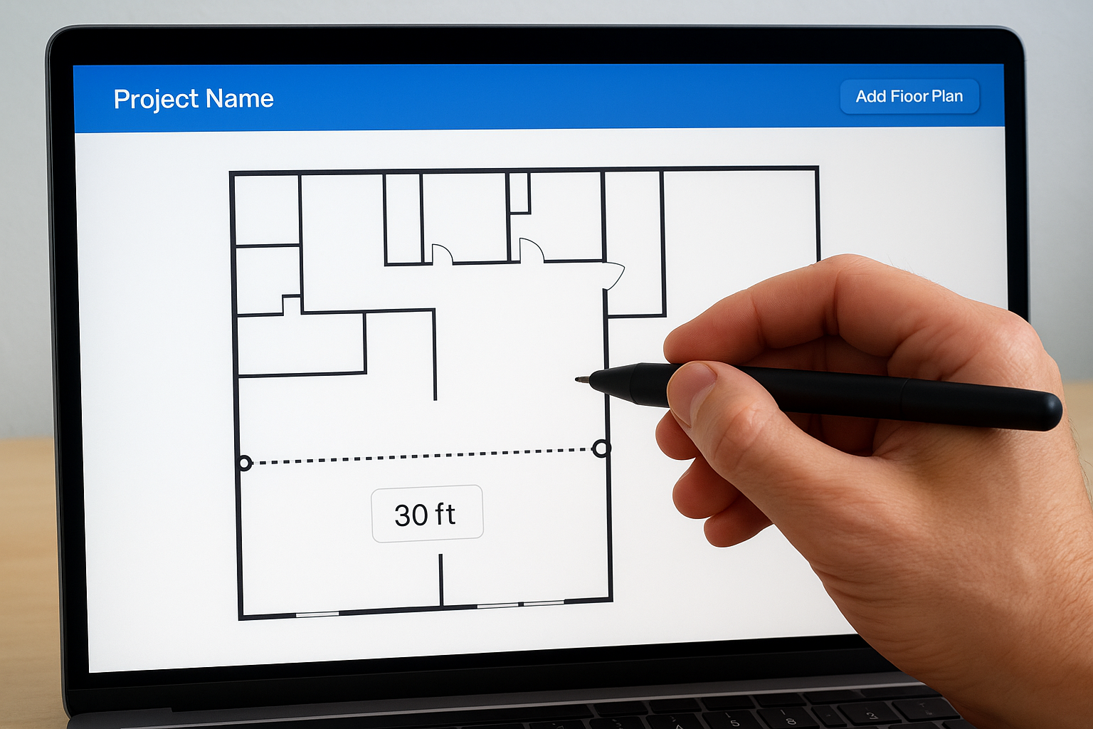
- Use an exterior wall for calibration, which tends to be more reliable than interior partitions
- Confirm measurements against your architectural plans or a site tape measure
- Re-check the scale if your building layout has irregular geometry
Step 2. Place WiFi access points and run coverage checks
With your floor plan scaled and ready, open the device library on the left panel of the Ubiquiti Design Center and filter by access points. Select a specific AP model, such as the U6 Pro or U6 Enterprise, and click anywhere on your floor plan to place it. The tool immediately renders a signal heatmap showing coverage radius, signal strength gradients, and potential dead zones across your space.
Adjusting AP placement
Move each AP by dragging it across the floor plan and watch how the coverage heatmap updates in real time as you reposition devices. Aim for overlapping coverage zones of roughly 15 to 20%, which provides roaming continuity without creating interference problems between neighboring APs.
Place APs closer to high-density areas like conference rooms or production floors first, then fill in secondary zones around the perimeter.
Checking for gaps
Switch the view to signal strength mode to highlight weak zones in red or orange. Add APs to fill gaps, or swap to a higher-gain model if the layout makes dense placement impractical.
- Red zones indicate signal below -70 dBm, which is too weak for reliable data transfer
- Adjust transmit power settings per AP to reduce co-channel interference in tight or high-density spaces
Step 3. Add cameras and confirm field of view
Switch to the camera planning mode in the Ubiquiti Design Center by selecting the camera tab in the left panel. This separates your camera layout from the WiFi design so you can work on each independently without the views overlapping and becoming hard to read.
Selecting camera models and placing them
Filter the device library by UniFi Protect camera models, such as the G5 Bullet or G4 Dome, and drop each one onto your floor plan at the intended mounting location. The tool renders a field-of-view cone instantly for each camera, showing the covered area based on that model’s actual lens specs.
Place cameras at entry points, loading docks, and high-value storage areas first, then fill in secondary zones around the perimeter.
Confirm that your selected camera model matches what you actually plan to buy, since lens angle varies between models and changes how the cone renders on the plan.
Adjusting angle and mounting height
Click any placed camera to open its property panel, where you can rotate the field-of-view cone and set mounting height in feet. Adjusting height changes the effective ground coverage area, which is critical for capturing usable footage rather than steep overhead angles.
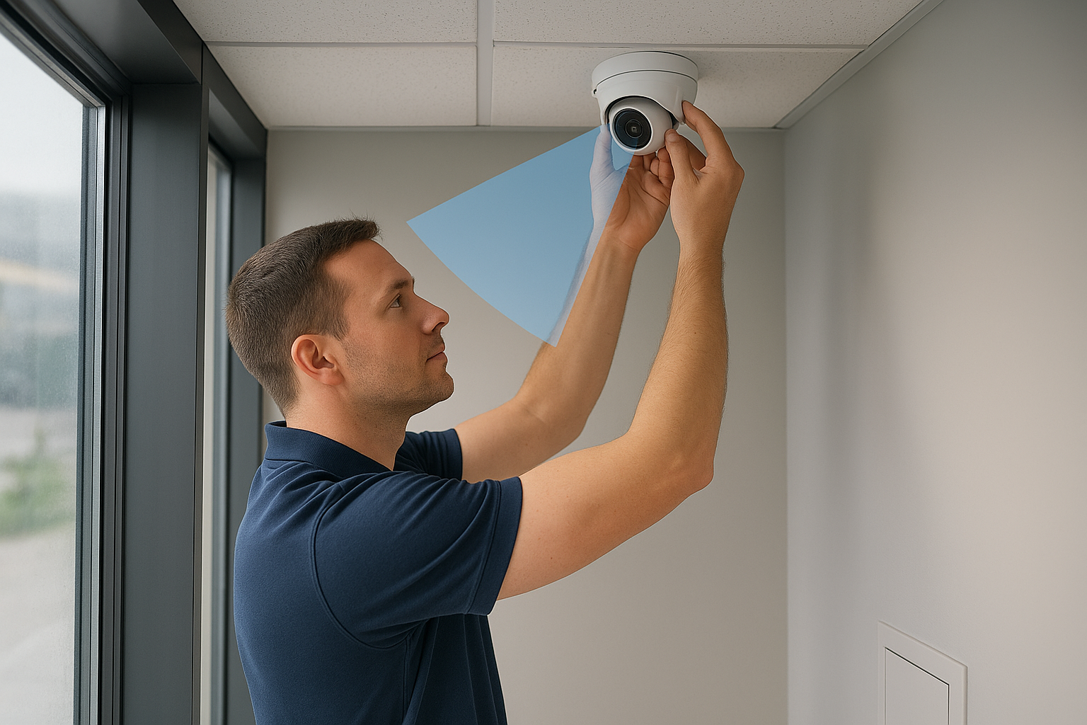
- Set mounting height between 8 and 10 feet for most indoor commercial spaces
- Rotate each cone so adjacent cameras overlap slightly to close any blind spots
Step 4. Verify cabling, PoE budget, and rack needs
Once your APs and cameras are placed in the Ubiquiti Design Center, open the built-in equipment summary to review the total device count and PoE power draw for your design. This list forms the starting point for sizing your switches and estimating rack space before you finalize anything.
Check your PoE budget
Each UniFi switch carries a rated PoE watt budget, and exceeding it causes devices to fail to power on or drop offline unexpectedly. Compare your total placed-device wattage against your planned switch’s rated PoE output to confirm you’re within a safe operating range.
If your total wattage exceeds 80% of the switch’s PoE budget, plan for a second switch or a higher-capacity model before finalizing the design.
Plan your cabling runs
Use the floor plan to trace cable paths from each device back to your MDF or IDF closet. Flag any run that approaches the 295-foot (90-meter) limit for copper Ethernet, since those may require a fiber segment or an additional IDF location to stay within spec.
- Count the total Cat6 drops required per closet
- Note which APs need multi-gig switch ports (2.5G or 10G) based on the model specs
- Add 10% to your cable count to account for failed pulls or future device adds
Next steps
The Ubiquiti Design Center gives you a concrete plan to work from before a single cable gets pulled or a bracket goes on the wall. You’ve now got a scaled floor plan, a tested WiFi coverage layout, confirmed camera fields of view, and a PoE and cabling summary that reflects your actual device list. That package is enough to get accurate contractor quotes, finalize your switch selection, and walk a site visit with a clear picture of what goes where.
From here, export your finished design as a PDF or shareable project link and bring it into your procurement and installation planning. Review your cable run lengths against your IDF locations one more time, and confirm that every AP and camera model in the design matches your final purchase order before installation starts.
If you want a second set of eyes on your layout before you commit, reach out to the CommX Networks team to review your design.