
Every cable run, switch, and access point in a commercial facility starts as a line on a diagram. Knowing how to create a network diagram is the difference between a structured, scalable build-out and a tangled mess that costs you time and money down the road. Whether you’re planning a new warehouse in Fort Myers or expanding an office complex in Naples, a clear visual map of your network keeps every contractor, IT team member, and stakeholder on the same page.
A network diagram documents the physical and logical layout of your infrastructure, from MDF/IDF rooms and patch panels to wireless access points and security cameras. It’s a planning tool, a troubleshooting reference, and a communication document all in one. Without it, even experienced teams make costly assumptions about cable pathways, equipment placement, and capacity.
At CommX Networks, we’ve spent 18 years designing and installing commercial network infrastructure across Southwest Florida. This guide walks you through the full process of building a network diagram for a commercial facility, covering the tools, steps, and best practices we use on real job sites every week.
What a commercial network diagram includes
A commercial network diagram is not the same as the simple topology sketch you’d draw for a home office setup. In a commercial facility, you’re dealing with multiple floors, dedicated equipment rooms, dozens of devices, and cable runs that can stretch hundreds of feet. Before you learn how to create a network diagram that actually works on a job site, you need to understand what belongs in it and why each element matters to the contractors, IT staff, and facility managers who rely on it daily.
Physical layer components
The physical layer is the foundation of every commercial diagram. This tier documents every tangible piece of infrastructure, from the main distribution frame (MDF) room down to each individual wall jack and cable termination point. If a technician can touch it, it belongs on your diagram. Skipping this layer or treating it as optional leads to cable conflicts, missed equipment placements, and expensive corrections mid-project.
Getting the physical layer right at the start prevents costly rework during installation and gives your team a reliable reference for future moves, adds, or changes.
A complete physical layer section typically covers:
- MDF and IDF locations: The rooms or closets that house your core switching and patching equipment
- Cable runs: Cat6 or fiber pathways between distribution points and endpoints, including conduit routes
- Patch panels and patch cords: How field cables terminate and connect to active equipment
- Wall plates and ports: End-user connection points throughout the facility
- Power sources: UPS units, PDUs, and outlet locations tied to network hardware
Logical layer components
Beyond the physical wiring, your diagram needs to capture how traffic actually flows through the network. The logical layer covers IP addressing, VLANs, routing paths, and device roles. This information is what your IT team and any future network administrators will depend on when troubleshooting performance issues or planning an expansion.
Include the following logical elements in every commercial diagram:
| Element | What to document |
|---|---|
| Device IP addresses | Static IPs assigned to switches, APs, cameras, and servers |
| VLAN assignments | Which ports or devices belong to which virtual network segment |
| Subnet ranges | The IP ranges allocated to each VLAN or department |
| Routing paths | How traffic moves between segments or out to the internet |
| WAN connection | ISP entry point, modem/firewall placement, and handoff type |
Notation and labeling standards
A diagram without consistent labeling creates confusion the moment a second person opens the file. Every device, cable run, and connection point should carry a unique identifier that matches the physical label on the equipment itself. Use a naming convention that includes the location, device type, and sequential number. For example, IDF2-SW-01 identifies the first switch in IDF room 2, which makes cross-referencing between the diagram and the physical space fast and accurate.
Your diagram should also include a legend that explains every symbol, color code, and abbreviation used throughout. Without one, the document loses reliability as personnel change and institutional memory fades over time.
Step 1. Define scope, audience, and standards
Before you draw a single line, you need to establish what the diagram covers and who will use it. A network diagram built for a general contractor on a new warehouse build looks different from one handed to an IT director managing an existing office expansion. Getting this clarity upfront shapes every decision you make, from the level of detail you include to the file format you choose for distribution.
Determine the scope and audience
Start by writing out the boundaries of your diagram in plain terms. Scope defines which physical spaces and systems you’re documenting, while audience determines how much technical detail the final document needs to carry. A facilities manager may need a high-level overview showing equipment rooms and cable zones, whereas a network engineer needs exact IP addresses, VLAN tags, and port assignments on the same drawing.
If your diagram tries to serve every audience at once without clear structure, it ends up serving none of them well. Consider building separate views layered on the same base diagram.
Answer these questions before you open any diagramming tool:
- What facility areas does this diagram cover? (specific floors, buildings, or zones)
- Who will read and act on this diagram day-to-day?
- What systems are in scope: data, voice, wireless, security cameras, or all of the above?
- Does this diagram support a new build, an expansion, or an existing infrastructure audit?
Choose your documentation standards
One of the most overlooked steps when learning how to create a network diagram for a commercial facility is selecting a consistent set of symbols and naming conventions before any drawing begins. Industry-standard symbols from ANSI/TIA give your diagrams a shared language that any qualified technician can interpret without additional explanation, which matters especially when multiple contractors work the same job site.
Apply a naming convention template from day one. Use this format as your starting point:
| Component | Format | Example |
|---|---|---|
| MDF room | MDF-[Building]-[Room#] | MDF-A-101 |
| IDF room | IDF-[Floor]-[Room#] | IDF-2-204 |
| Switch | [Location]-SW-[##] | IDF-2-SW-01 |
| Access point | [Location]-AP-[##] | FL2-AP-03 |
| Camera | [Location]-CAM-[##] | WH1-CAM-07 |
Every label on the diagram should match the physical label on the equipment itself. That one-to-one relationship is what turns a diagram into a reliable field reference rather than an outdated document that technicians ignore.
Step 2. Map the physical layout and cabling
With your scope and standards locked in, the next move is to get the physical reality of the facility onto paper. This is where many teams rush and pay for it later. Start by pulling the building’s floor plan into your diagramming tool as a background layer. If a digital floor plan isn’t available, measure the space yourself and sketch a basic layout to scale. Every room, hallway, and equipment closet you draw now becomes a reliable anchor point for every cable run and device placement that follows.
Identify equipment room locations
Pinpoint every MDF and IDF room on the floor plan before adding anything else. These rooms are the structural backbone of your diagram, and every cable run originates or terminates at one of them. Mark the physical dimensions of each room and note available rack space. If the facility has multiple floors, draw a vertical riser diagram alongside the floor plan to show how backbone cabling connects each IDF back to the MDF.
Getting equipment room positions right before you add cable paths prevents you from designing routes that are physically impossible to pull in the field.
Trace cable runs and pathways
Once your equipment rooms are placed, trace every horizontal cable run from each IDF to its endpoint zones. Follow the actual conduit and pathway routes the cable will travel, not the straight-line distance between two points. Mark the approximate length of each run so you can flag any segment that risks exceeding the 295-foot (90-meter) maximum for horizontal Cat6 runs defined by the TIA-568 standard.
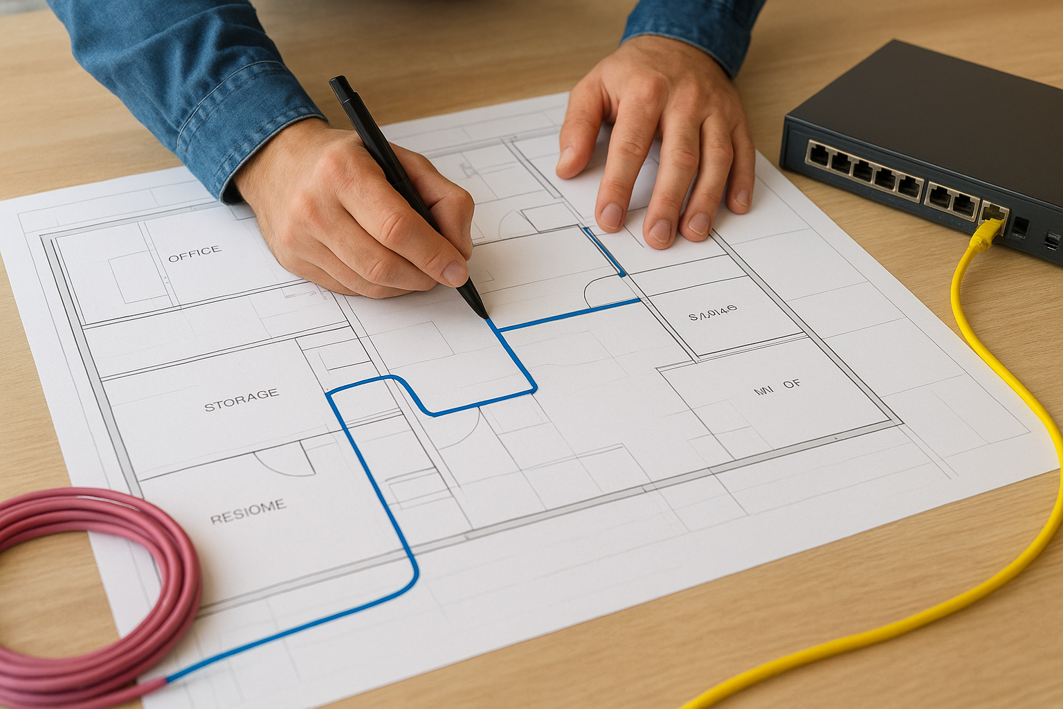
Track each cable segment in a run table as you draw it:
| Run ID | From | To | Cable Type | Est. Length (ft) |
|---|---|---|---|---|
| CR-01 | MDF-A-101 | IDF-2-204 | OM3 Fiber | 180 |
| CR-02 | IDF-2-204 | FL2-AP-03 | Cat6 | 120 |
| CR-03 | IDF-2-204 | WH1-CAM-07 | Cat6 | 210 |
Filling this table in parallel with your diagram keeps your drawing and your documentation in sync, which is one of the most practical habits when learning how to create a network diagram that holds up through an entire project lifecycle. Update both every time a route changes so neither document drifts from reality.
Step 3. Add devices, IP details, and traffic paths
With your cable runs mapped, you’re ready to populate the diagram with every active device and the logical details that define how your network actually operates. This step is what separates a cabling sketch from a proper network diagram, and it’s where knowing how to create a network diagram pays off in real troubleshooting and expansion scenarios.
Place and identify every device
Start by placing each device symbol at its physical location on the diagram. Use your standard symbol set to represent switches, routers, firewalls, wireless access points, IP cameras, and servers. Every symbol should carry the device’s unique identifier from your naming convention, the model number, and the port count if it’s a switch.
A device symbol without a label forces your team to cross-reference other documents every time someone reads the diagram, which defeats its purpose as a field reference.
Here’s a quick reference for what to attach to each device:
| Device | Label Required | Additional Detail |
|---|---|---|
| Core switch (MDF) | MDF-A-SW-01 | Model, total ports, uplink type |
| Distribution switch (IDF) | IDF-2-SW-01 | Model, uplink port to MDF |
| Access point | FL2-AP-03 | Model, PoE source port |
| IP camera | WH1-CAM-07 | Model, PoE source port |
| Firewall/router | MDF-A-FW-01 | WAN interface, LAN interface |
Document IP addresses and VLANs
Once devices are placed, add the static IP address and VLAN assignment to each node directly below the device label. Color-code each connection line by VLAN so traffic segments are visible at a glance. For example, assign blue to your data VLAN, red to your security camera VLAN, and orange to your voice VLAN. This color system lets any technician identify network segments instantly without reading every label.
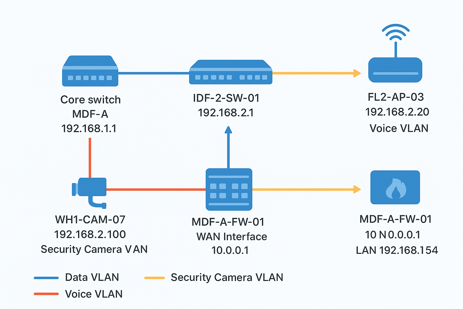
Draw traffic path arrows between network segments to show how data flows from endpoints through distribution switches to the core, and then out through the firewall to the WAN. These arrows give any engineer reviewing your diagram an immediate grasp of your routing logic without needing to dig through device configuration files.
Step 4. Validate, label, and maintain the diagram
A finished diagram is only useful if it matches physical reality. Before you hand off or file any version of your network diagram, walk the installation with the document in hand and verify that every device, label, and cable run reflects what was actually built. Skipping this step turns your diagram into a liability rather than a reliable reference.
Verify accuracy against the physical installation
During your walkthrough, cross-check each physical label on the equipment against its corresponding identifier on the diagram. If IDF-2-SW-01 is labeled on the switch faceplate, that exact string must appear on the diagram with no variation. Document every discrepancy in a punch list and resolve each one before you mark the diagram complete.
A diagram that doesn’t match the physical installation will mislead the next technician who opens it, costing time during a live troubleshooting event.
Use this checklist to structure your validation walkthrough:
- Every device label on the diagram matches the physical label on the hardware
- All cable runs are confirmed with a cable tester and lengths are updated in the run table
- IP addresses and VLAN assignments match device configuration files
- All ports in use are documented; unused ports are marked accordingly
- The legend and symbol key reflect every notation used in the final diagram
Establish a version control and update process
Learning how to create a network diagram is only half the work. The other half is keeping it current. Every time you add a device, extend a cable run, or reassign a VLAN, update the diagram the same day and increment the version number in the title block. A title block should sit in the lower-right corner of every diagram page and include at minimum the facility name, version number, revision date, and the name of the person who made the change.
Store the master editable file in a shared location that your IT team and facility manager can both access. Distribute a read-only PDF export with each new version for field reference, while keeping the source file protected to prevent unauthorized edits that create conflicting versions.
What to do next
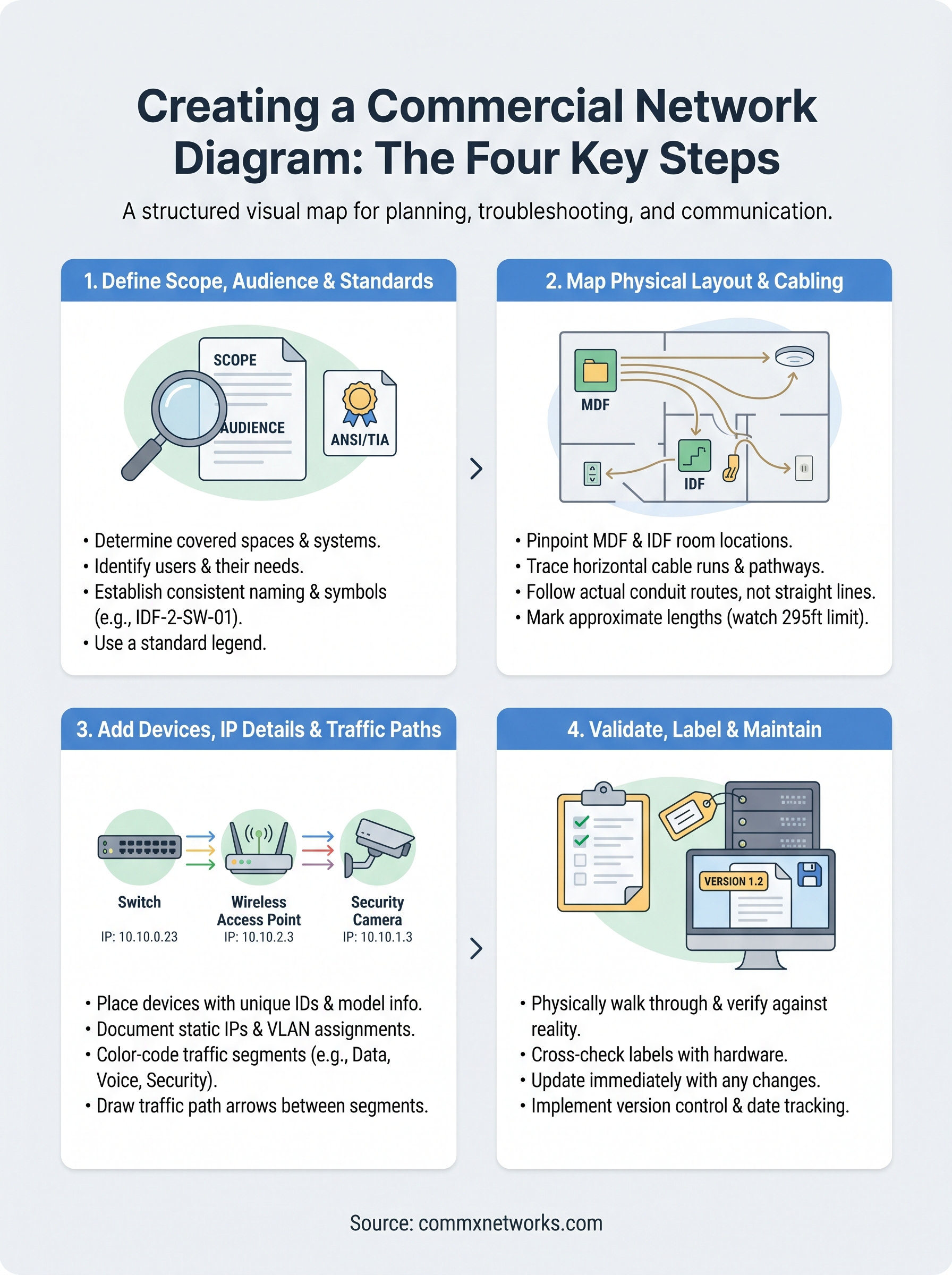
You now have a complete framework for how to create a network diagram that holds up through design, installation, and every change that follows. Start with your scope and standards, build out the physical layer from equipment rooms to endpoints, add your device labels and IP details, then validate every element against the actual hardware before you call the diagram final. Each step builds on the last, so resist the urge to skip ahead to device placement before your cable routes are confirmed.
For most commercial facilities, getting this right the first time requires more than a good process. It requires experienced hands who understand the physical environment before a single cable is pulled. If you’re planning a network build-out or expansion in Southwest Florida and want the infrastructure done correctly from the start, contact the CommX Networks team to walk through your project and get a plan that matches your facility’s real-world demands.